Progress Logs Continued
Any research conducted or progress made on the project are documented in this section.
Week 37 - 04/14-04/20
The final week was spent on testing, the final report and powerpoint presentation. The goal was to run tests for the power analysis, monitor the temperature of the compartments in both outside and inside conditions, measure the solar panel power, test the USB and wireless charging rates, the speaker decibel levels, and the car battery charging. Unfortunately, there were issues trying to get a measurement for the car charging. The car port voltage was measured at 13.6V. However, attempts at measuring the current were not working. The circuit was broken at one of the battery terminals and the multimeter completing the connection, but no current was measured.
Reuben - First the power was analyzed for the system by breaking the circuit at the battery and measuring the current. After testing, realistically the system only consumes about 1A when in full operation. The system current consumption was testing by breaking the circuit at the battery and using a multimeter to measure. The following table show how when a feature is added, the current goes up. Initially current is about 410 mA with the power on and the Raspberry Pi and touchscreen running.
These components affected the batteries the most and as each function was powered, the current consumption increased till it reached about 1A. The system can run with everything powered for about 28 hours. However, if the system is used moderately, it can run for several weeks.
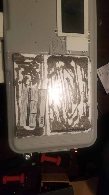
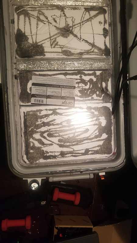
To test the temperature retention in the cooler, tests were conducted both in an outside and inside environment. First the tests were conducted outside. The tests that needed to be done were to monitor the temperature when there is no ice in the cooler, where there is ice in one compartment only, when there is ice and food in one compartment only, when there is ice in both compartments, when there is ice and food in one compartment and ice in the second compartment, and when there is ice and food in both compartments. The tests with no ice inside the compartments were only run for an hour to provide a control measurement. The rest of the tests were run in a three-hour period and temperatures were recorded every half an hour due to limited time. When ice or food was placed into the compartment, the majority of the space was filled. About 15lbs of ice was placed into each compartment. The picture shows how the compartments with both food and ice were filled.
Note that when both compartments have ice in them, the temperatures are about the same for both compartments. The outside temperature does not affect the inside temperature of the cooler. When ice is in one compartment and no ice in the other compartment, the other compartment does a good job of maintaining its temperature. The lowest temperature reached was 37.6⁰F. Next, the cooler was placed inside a house as the inside environment where the temperature was maintained at 76⁰F.
Next, the solar panel power was measured. The ratings found on the back of the solar panel are shown in the figure below.
The panel is rated to have an open circuit voltage of 22.41V and a short circuit current of 610mA. The panel is also rated for 10W. To measure the open circuit voltage, the solar panel was disconnected, and a multimeter was used to measure the voltage across the panel. The following figure below shows the results, where the voltage was measured during a partly cloudy, which is why there are so many peaks. The max voltage recorded was 21.6V when the sun was exposed but went down the lowest of 18.4V when a cloud covered the sun. The short circuit current was measured the same way as the voltage was measured. The highest recorded current measurement was 364mA when the sun was bright and the lowest recorded was 15.2mA when a cloud covered the sun.
The wattage was calculated by using the power equation. The max wattage recorded was 7.9W while the lowest recorded wattage was 275mW.
To test the USB charging and wireless charging of the system, an iPhone and Android phone were used. The iPhone was tested on the USB charger on the cooler, while the Android was tested on the wireless charger. The figure below compares using the cooler USB charger, which is 5V 2.1A, and the iPhone power adapter, which is 5.2V 2.4A. The plot shows that the charging capabilities are very similar. For the Android, the wireless charging pad was compared to the Android phone power adapter. The wireless charging pad is rated for 5V 1A charging, while the Android power adapter is rated for 5V 2A. It can be seen from the figure below that the power adapter took approximately 100 minutes to charge, while the wireless charging pad took 220 minutes. Since the wireless charging is rated for less amps, it would make sense that the charging takes longer.
In order to measure the decibel rating of the Bluetooth speakers, a sound meter app called “Decibel X” was downloaded on an iPhone. The table below shows the decibels for a comfortable listening level at about 78dB. When the speakers were set to max volume, the decibels were at 89dB.
Week 36 - 04/07-04/13
Clarence - Final fully loaded testing. The compartment was filled with 20 lbs of ice to monitor how low the temperature gets and how long it takes. After 1 hour the temperature was recorded to be 39.9 Degrees.
With the temperature below 40 degrees some common food items were put in the cooler to track how the temperature behaves when food is in it. Several canned sodas, beef patties, and icecream were put in the cooler and the temperatures were observed for 8 hours.
The findings of this test are in the graph below
Week 35 - 03/31-04/06
Reuben - Quarantining because of COVID.
Clarence - The cooler was taken to a heavily wooded area to test the mobile apps connectivity to the unit.
While under heavy tree cover an android phone was used to control the cooler through the mobile app. The app was able to consistently control the cooler at a range of 25 meters.
While in the wooded area the GPS module was turned on and accurately tracked the location of the cooler and connected with Google to generate directions to the location.
The charging function of the solar panel during actual operation. While the cooler was in a well lit area with direct sunlight and the voltage from the charger was measured to be 13.33 volts. The circuit was broken at the battery and then at the terminal block directly after the solar panal’s distribution box. Neither gave a recordable current value. This could either be because the batteries still have quite a large charge on them from the previous round of testing, or it could be due to the software and electronics in the distribution box interfering with the current.
Week 34 - 03/24-03/30
Reuben - Quarantining because of COVID.
Clarence - I was able to run several tests over the weekend, with some light touch up fabrication. I also weighed the unit without ice. The weight of the unit is 43lbs.
Because I planned to test the cooler outside overnight I started by fabricating a cover for the 120 Volt AC connection. With the cooler exposed to the elements and possibly condensation in the early morning hours I wanted to make sure that the plug would not be exposed to any liquids.I made the plug out of an extra plug that we have and I secured it to the cooler using the water proof 2 part epoxy.
With the cooler secure I moved onto testing the systems. With so many systems I was able to test several at the same time to save time. The first test validated the RFID Reader and the Locking mechanism. The procedure is in the video below and I did this 50 times with no errors proving that the RFID reads reliably and the lock is no longer fouling.
The next test was to see how the unit retained ice and behaved when exposed to the elements. The unit was charged and both compartments were filled with 5 lbs of ice and then monitored through the night with all of the functions and systems on.
The test started at 4 PM on Sunday March 27 and ended at 1 PM on Monday March 28. The cooler condition was checked every 3 hours and the results are below.
This test confirmed that ice retention exceeds 12 hours, the batter will support full operation for at least 21 hours.
Week 33 - 03/17-03/23
Next, the locking mechanism was having issues as the sliding lock was not locking all the way because it was hitting the lid bracket. The issue was that the dowel was loose, so in order to fix this, instead of using wire to secure the dowel, a nut and bolt was used instead. The servo horn needed to have a bigger hold to hold the bolt, but otherwise no other modifications needed to be made.
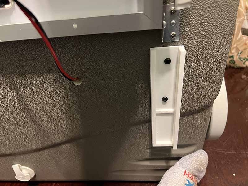
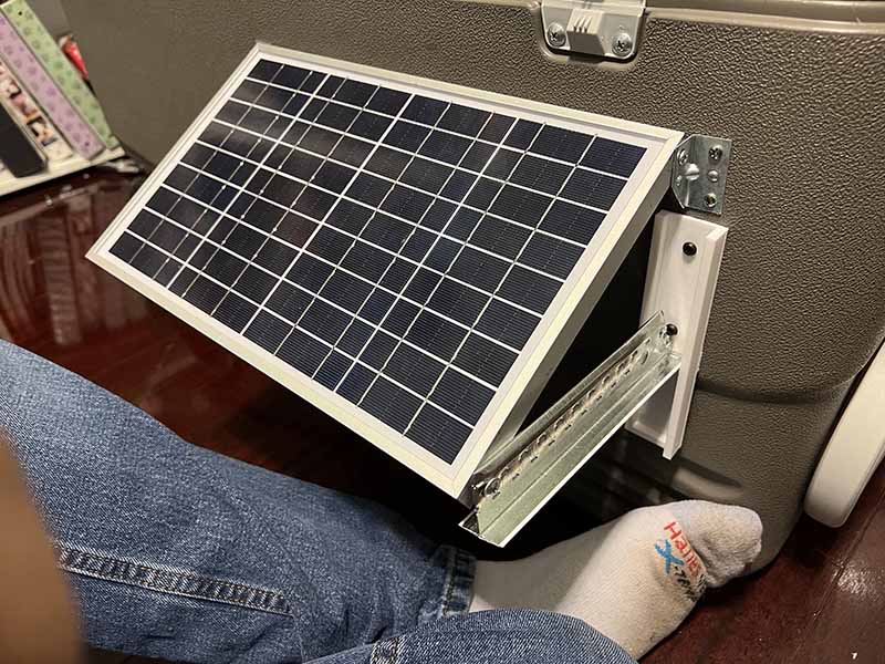
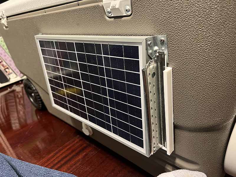
Finally, the bracket to hold the solar panel was fabricated. The goal was to have a metal bracket that would hold, so a trip to the hardware store came out with a cross tee used to hang ceiling tiles. The part was cheap and sturdy, and could be easily snipped into shape with tools already on hand. A bracket was 3d printed to allow an edge for the metal tee to hold. The bracket also holds the tee in place when it isn't used.
Week 32 - 03/10-03/16
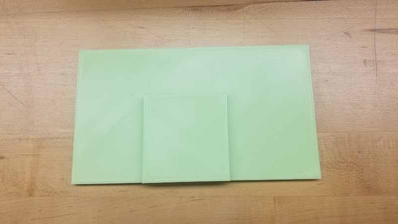
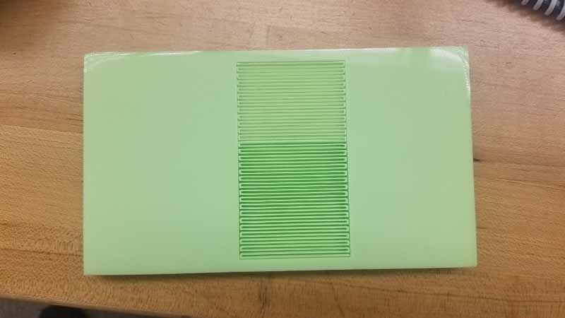
Clarence - This week the group met for an hour to discuss how to approach some of the issues that were encountered. We discussed how to address the lock reliability issue and will be looking into a new way to connect the servo to the bolt of the lock. I went to the 3D printing lab on campus to print the cover for the RFID locking compartment, and I cut the cover for the last compartment out of plexiglass.
Reuben - A few software updates were performed on the Raspberry Pi and tested. Firstly, the LED auto feature needed to be calibrated for when the cooler is placed in a dark setting. The cooler was calibrated by placing it in a room and turning the light off. The room was not completely dark as there was light from the window coming in. The auto light feature was approximated this way and will be tested more for more accurate performance. The software needed to be updated where when the auto LED light feature is activated, and the LED lights are pressed off on the touchscreen, the lights will still turn on and stay on when it is dark in the environment. An issue that occurred was then when the lights were turned off in the room and the LED lights would turn on, the light coming from the LED lights would tell the sensor that it is light outside and automatically shut off the lights again. The lights would continue to turn on and off constantly. To solve this problem, a variable was added in the program for when the auto feature is activated and it is light outside, then activate the lights and keep the lights on until the lid is closed again. That way, the ambient lights from the LED strips will not cause the lights to turn themselves off. The final result is in the following video. The video shows the lights being activated by turning the auto feature on, then the lid is opened and the room lights are turned off. The lights automatically turn on, and then the lid is closed and the lights turn off again.
The next feature tested was the auto lock feature. This was simply done by setting the locking feature to auto, and then closing the lid. The locking mechanism will automatically close when the lid is closed. To prevent the auto locking feature from locking itself when someone tries to open it, when the off button of the lock is pressed, there is a 3 second time delay that allows the user to open the lid. Once the 3 seconds are up, the locking mechanism will activate again. The following video shows the locking feature being set to auto. Once the lid is closed, the locking mechanism locks.
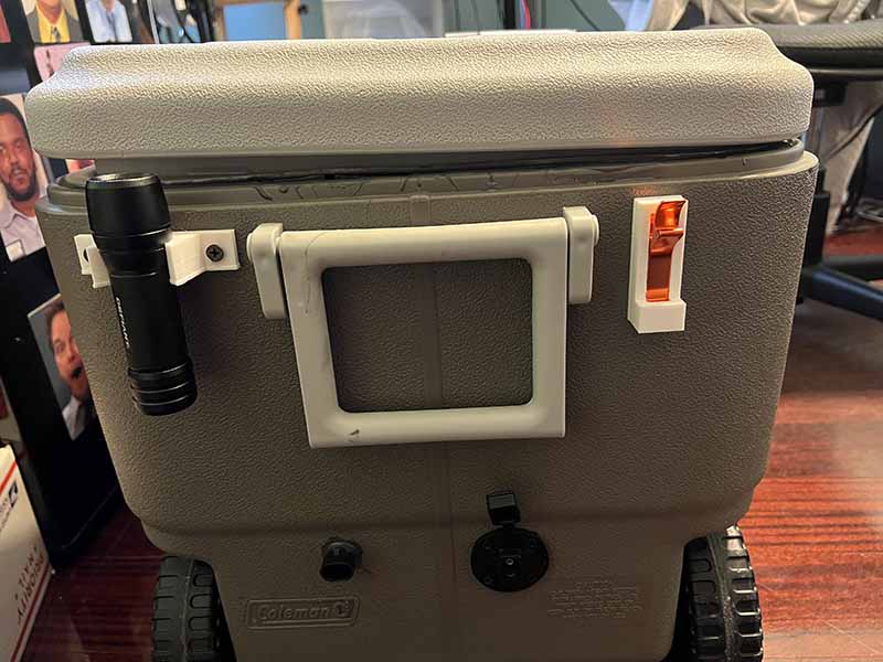
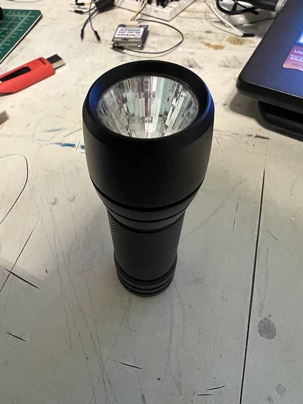
Next were some added features that have been neglected since the start of the project. The cooler is supposed to feature a flashlight holder and can opener. To install a flashlight holder, a small flashlight was purchased to be installed with the cooler, the cheapest being selected to keep the budget small. The important dimensions of the flashlight were where the head is located, as the flashlight holder will use the head to hold the flashlight. The dimensions of the head were measured at 1.2" diameter at its widest and 1.1" diameter at its narrowest. The height of the flashlight is 4.5" high. The following flashlight holder was modeled. The dimensions for the flashlight holder are 3" wide by 0.75" high.
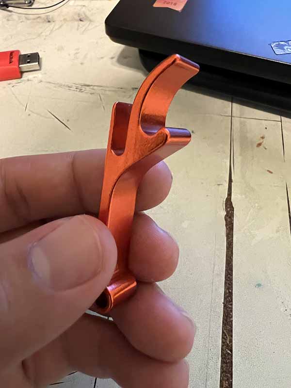
Next, the bottle opener was modeled. The bottle opener being used was not purchased but was found on hand. The bottle opener will slide into the modeled part, and will be secured. The dimensions are 2.4" high by 0.85" wide by 0.73" long.
Week 31 - 03/03-03/09
The first thing that was tested when the group met on Tuesday was the mobile app. The work on the mobile app had been mostly finalized and deployed to both iPhone and android phones for testing. Upon arrival at Clarence's house, the mobile app on the iPhone did not stay on the phone, so deploying to the iPhone needs to be redone. However, the mobile app was still on the android phone, so the android phone was used for testing. In the video below, the LED colors can be seen being changed through the android app.
Next, the locking mechanism was also tested through the mobile app. The video below shows the locking mechanism being activated through the app, and then Clarence trying to pry the lid open while it was locked, and then unlocking the lid through the app, where Clarence is then able to open the lid.
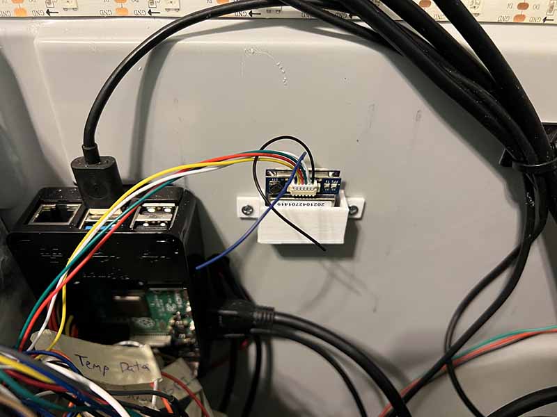
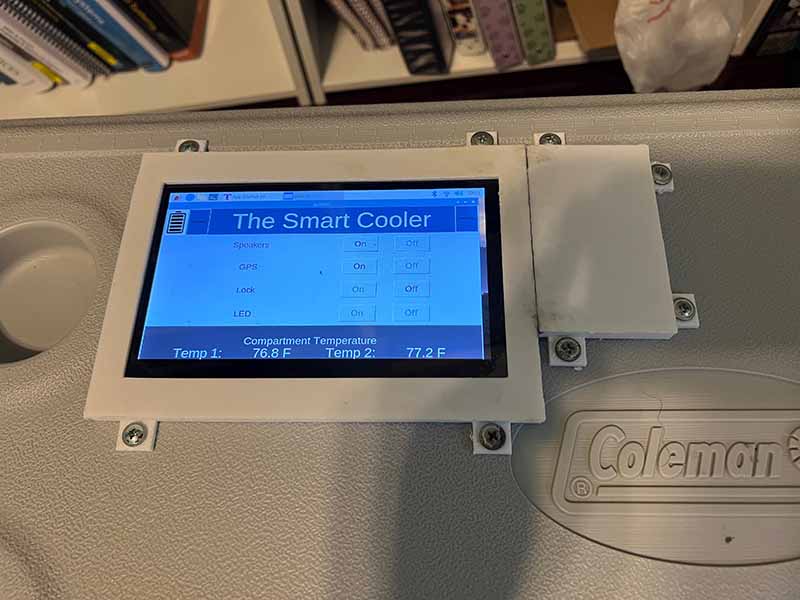
Clarence - The GPS module bracket and monitor bezel were mounted. The GPS module bracket was simply screwed next to the Raspberry Pi in the electronics compartment. The monitor bezel needed to be epoxied together as it was two separate pieces. The pieces were then made waterproof using silicon to seal the crack between the two parts. The locking mechanism covers were also installed for two of the parts.
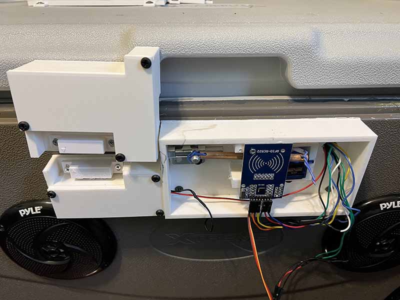
Reuben - Firstly, an issue occurred during the group meeting where the RFID and light sensor and battery sensor reading were not being processed by the Raspberry Pi. The error led to the conclusion that there was an issue with the SPI, as that is what both the RFID and analog to digital converter that the sensors use. It was determined that there was a wiring issue, that two of the wires were knocked out of place, though simple but difficult to find as it was hidden behind the wires at the bottom of the breadboard.
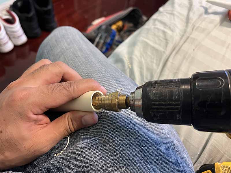
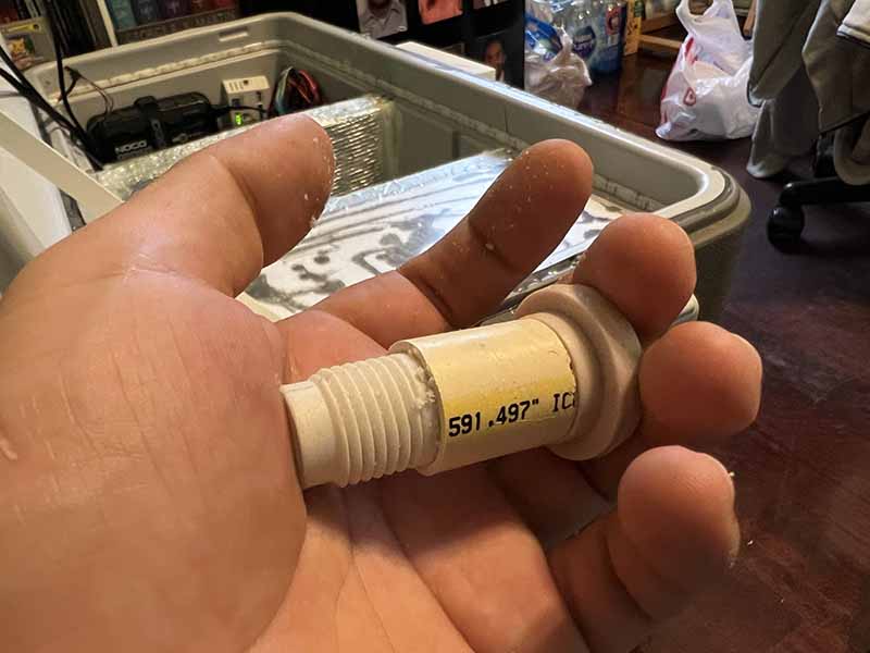
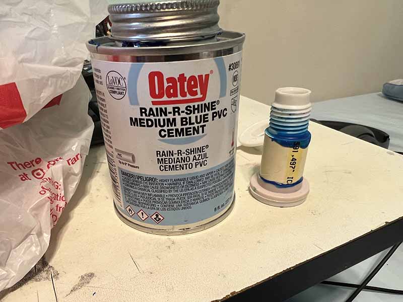
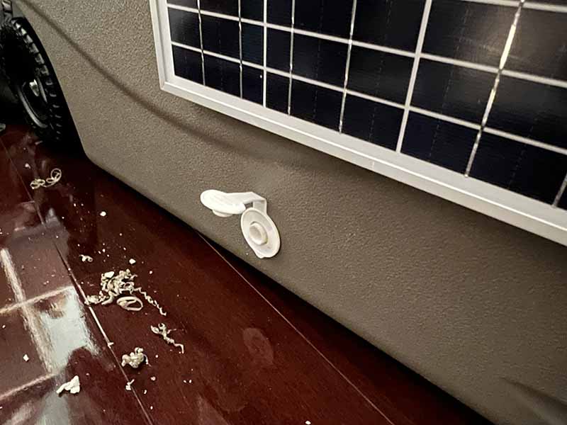
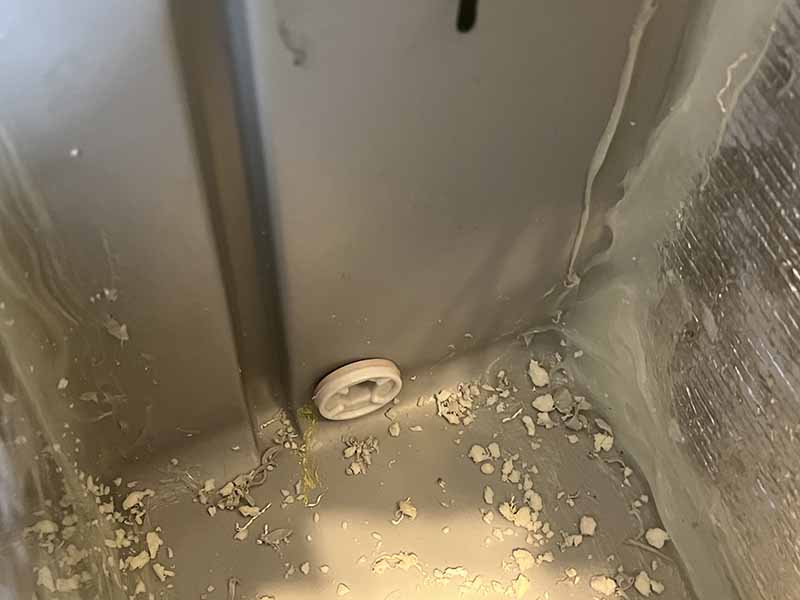
The next step was the drain plug. Since the cooler has a middle compartment, a drain plug needed to be installed in the middle to allow for easy drainage of the middle compartment. In order to get the drain plug to fit into the cooler, the plug needed to be modified. The drain plug was too short, so the best option was to split the plug piece and extend it using a piece of PVC pipe. A piece of 1/2" PVC pipe was cut and the interior was drilled slightly wider on both sides using a unibit to fit the drain plug pieces. The pieces were then glued together using PVC cement, as that would provide a watertight seal. The plug was then fit into place.
Week 30 - 02/24-03/02
The group met to do a leak test of the cooler compartment and discuss possible draining options. After continuing to test for leaks it was decided that a drain plug would be needed for the second compartment to help with draining and making sure that the compartment can be drained without the risk of damaging the electronics. The current method of draining the second compartment is by tipping the entire cooler over. This is not practical as if it is tipped the wrong way, water can get into the electrical part of the cooler.
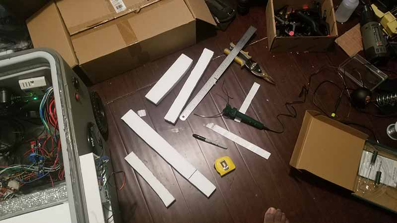
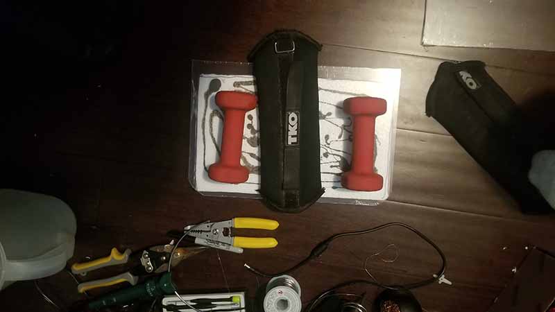
Clarence - This week for fabrication the focused was on the completion of the lids that will be used to cover the compartments. The lids are made with plexiglass and styrofoam. Using these will allow the compartments to be able maintain different temperatures. First, the styrofoam was cut into shape for each compartment. The tool used to cut the styrofoam was a styrofoam hot wire. Next, the styrofoam was epoxied to the plexiglass.
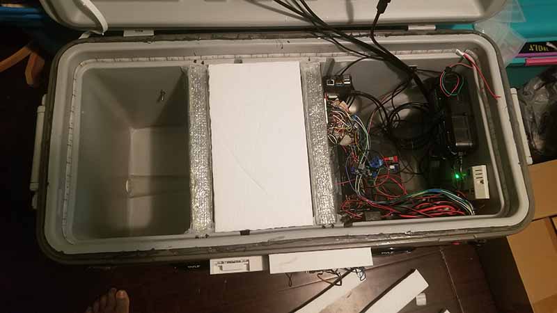
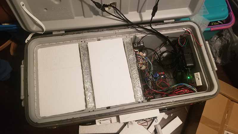
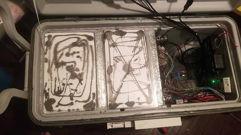
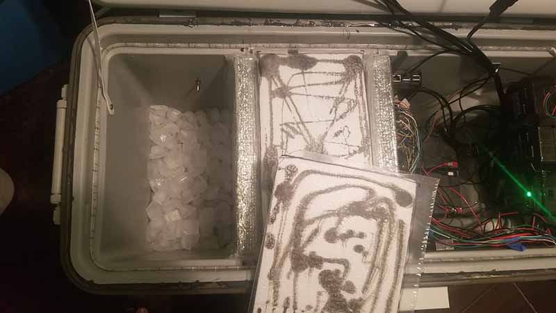
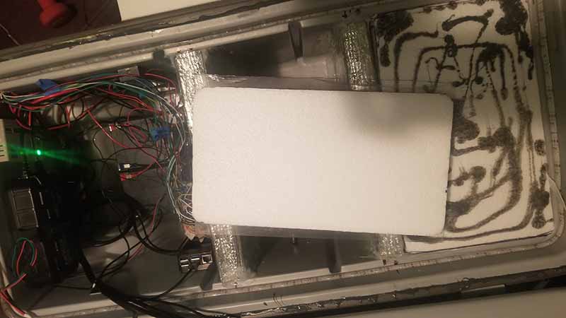
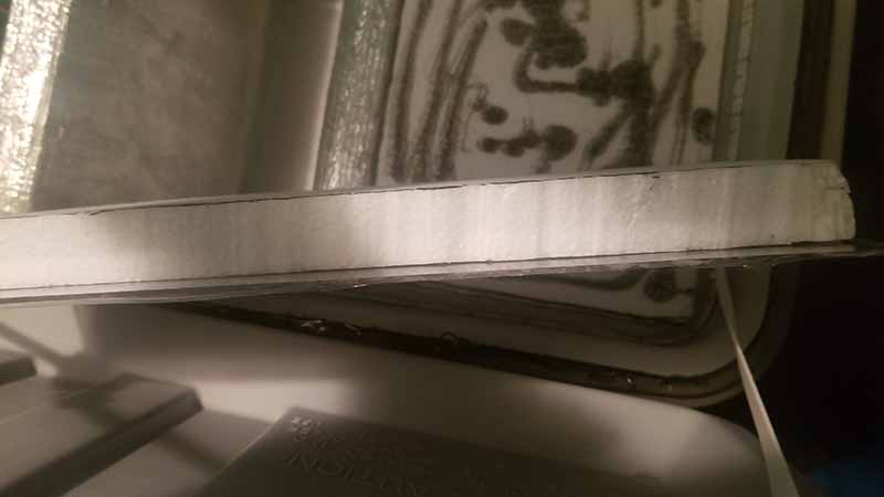
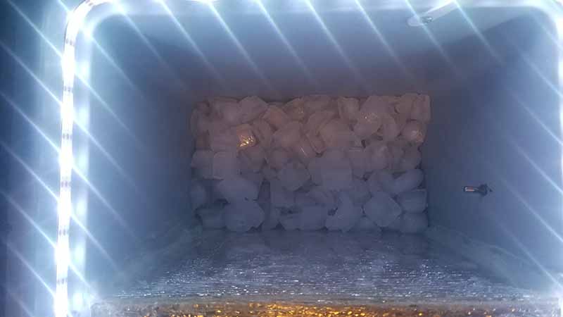
With the compartment lids constructed the first compartment was tested. Roughly 5 lbs of ice were placed in the compartment and this lowered the internal temperature by 20 degrees. After 12 hours the temperature was maintained and most of the ice was still solid. At the 18 hour mark there was noticeable melting however the temperature was still 20 degrees lower then the compartment with no ice, and at the 24 hour mark most of the ice was melted but the temperature was still 20 degrees colder.
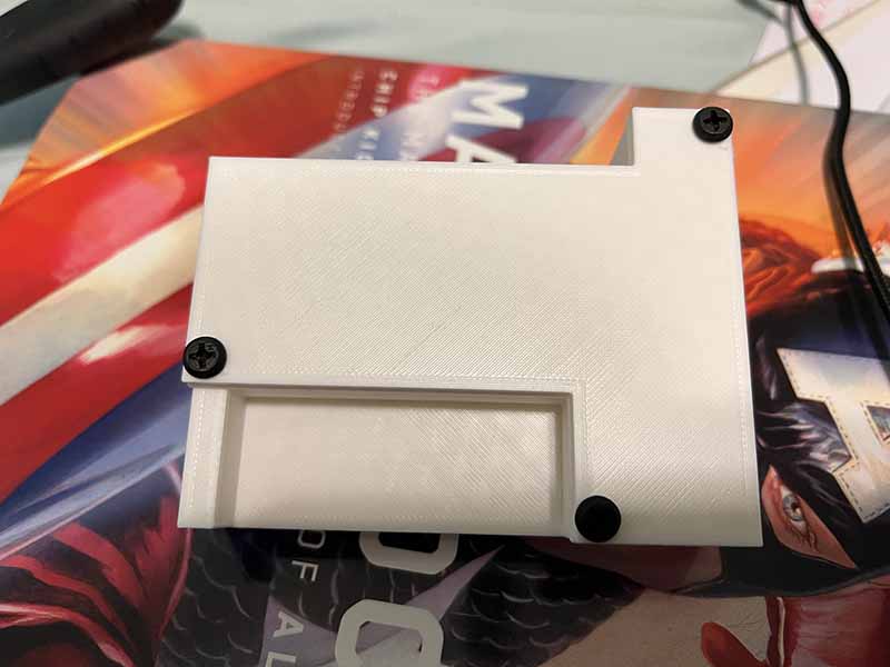
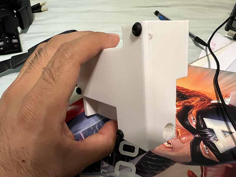
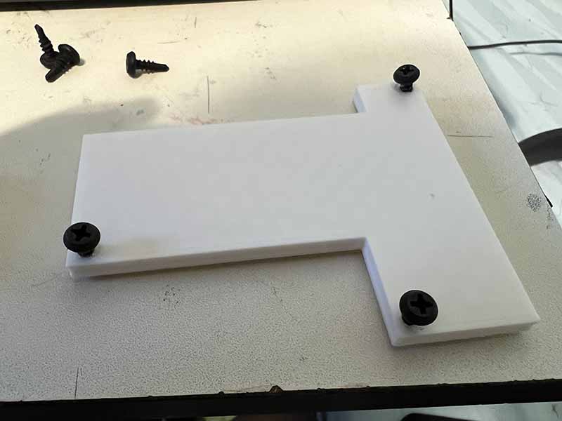
Reuben - The covers for the locking mechanism was printed. There needs to be three separate covers, one for the lock lid bracket case, door sensor cooler case, and lock cooler case. The lock lid bracket cover and door sensor cover were printed. However, due to running low on ABS plastic, new material was purchased and some issues occurred while trying to print the last cover. There was warping and scrapping, so there needs to be adjustments made to the print settings.
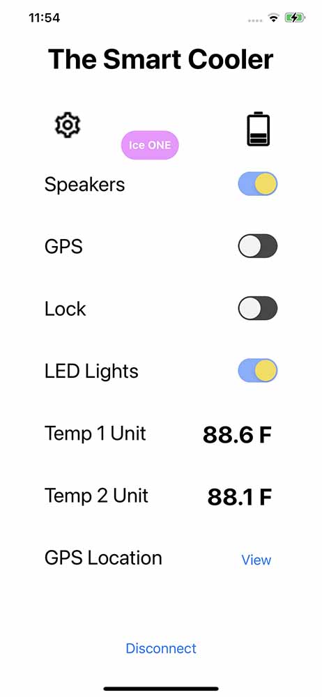
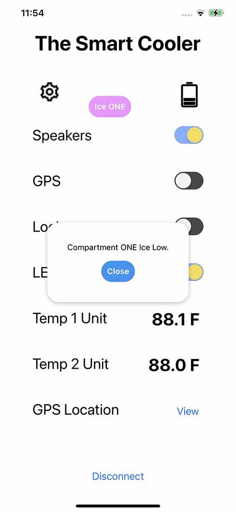
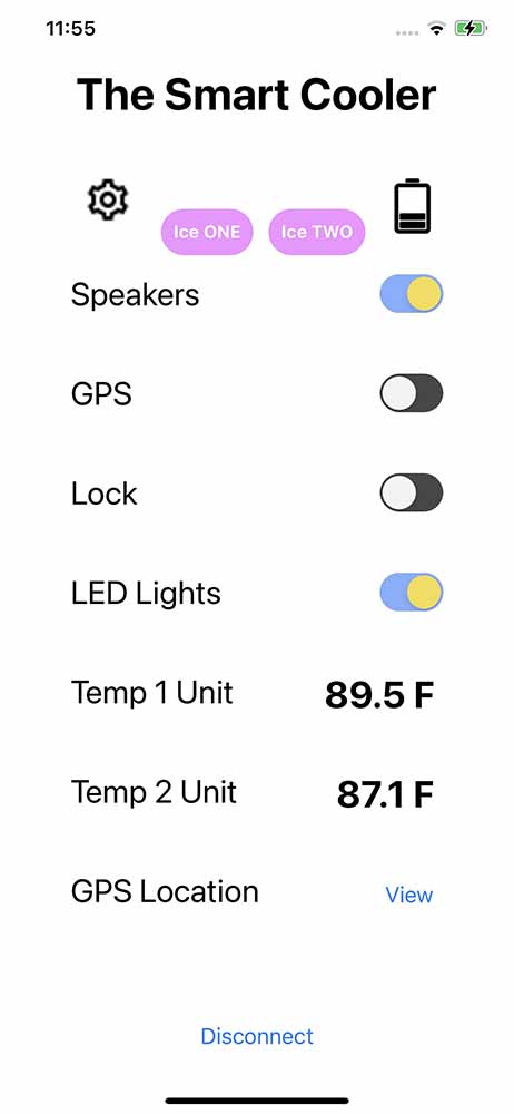
Work was also done on the mobile app. The ice notification is now displayed on the app. To activate, first, the ice notification must be enabled from the cooler GUI. Then, when the temperature goes above a certain range (in this case set to above 30 degrees Celsius for testing purposes), the low ice notification will display on the touchscreen GUI, meanwhile the app recieves the ice notification on message and will display a pink button when activated. Clicking on the button produces a modal window that displays the message that the ice is low. To deactivate it, the user must go to the cooler and close the notification window, which will make the ice notification disappear on the app. The image on the left shows when the ice notification for compartment one is activated. The middle image shows the modal window that appears when the "Ice ONE" button is pressed. The image on the right shows when the ice notification is enabled for compartment one and two, where a button will appear for each compartment.
Week 29 - 02/17-02/23
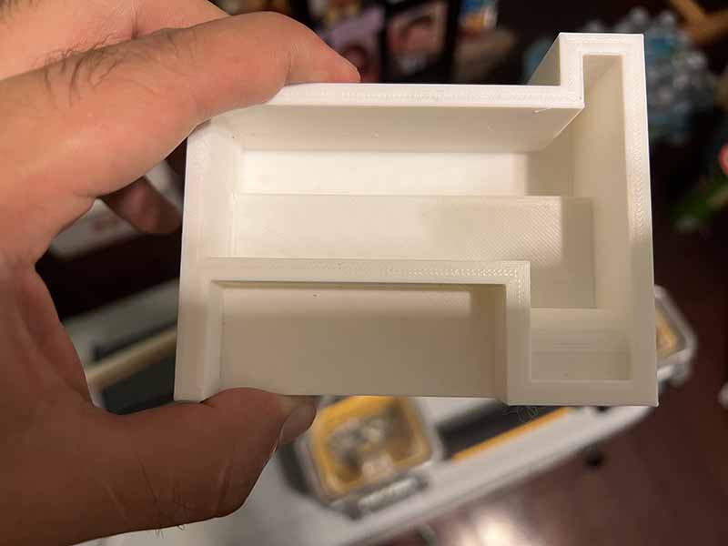
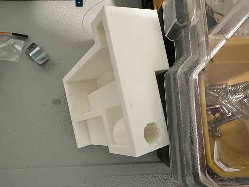
Reuben - Work was done on the locking mechanism. The locking mechanism consists of three 3d printed parts. First, the lock lid bracket that contains a recess hole for the sliding lock to fit into, and a slot for the door position sensor to be placed. The dimensions are 4" long by 3.25" high by 1.5" wide. The piece is created into a hollow shape to allow for it to be screwed to the lid. A cover will be 3d printed that will screw on top.
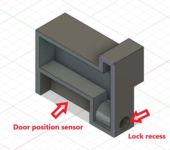
The part took approximately 11.5 hours and 82g of ABS plastic to print. The results are shown below.
The next part to print was the bracket for the door position sensor that was located on the body of the cooler. This part will simply have the door position sensor, and wire connecting to the sensor. In order to run the wire, a drillbit will be used to create a hole into the plastic. The dimensions for this piece are 4" long by 2" high by 1" wide. This piece was also created hollow to allow for wire to run through it, as well as allow it to be screwed to the body of the cooler.
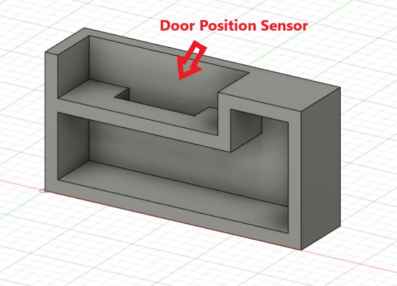
This part took 5 1/2 hours to print and 39g of ABS plastic. The results are shown below.
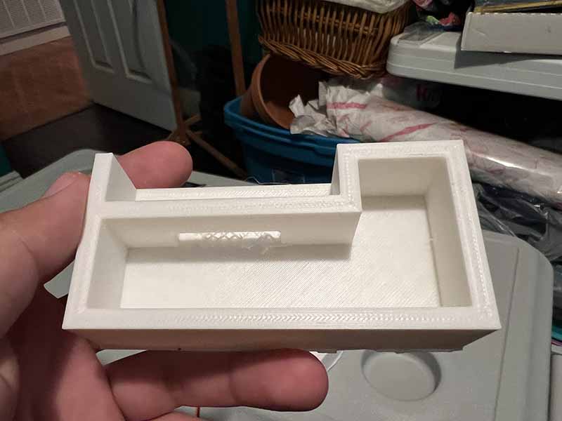
The final piece of the locking mechanism is going to house the sliding lock, RFID, and servo. This part was modeled to just be open space, as the sliding lock was going to screw into it, as well as the servo bracket that was designed earlier. There is a platform for the RFID to mount, so that the RFID is closest to the front of the part. When the cover is printed for this piece, it will be modified to allow room for the RFID and indicate where the RFID tag needs to be placed to be read. A hole was also modeled where the sliding lock will be placed, so that the sliding lock can protrude out of the piece. The dimensions of this part are 7" long by 3.5" high by 1.25" wide. The part was created hollow to allow for wire to be run inside, as well as allow for screwing of parts to the cooler.
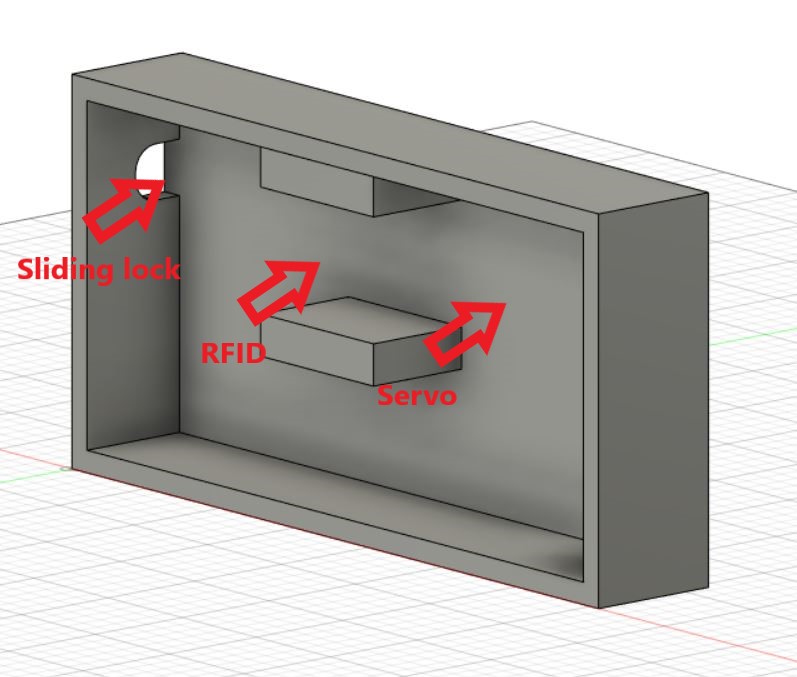
The part took approximately 14 1/2 hours to print and 108g of ABS plastic to print. The results are shown below.
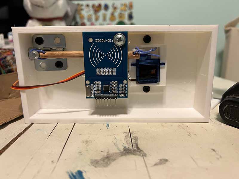
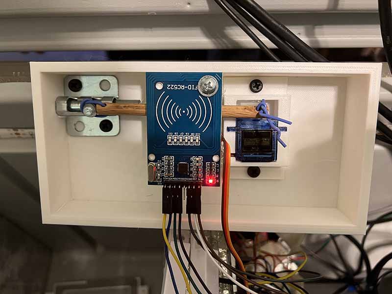
The following video shows the locking assembly being tested. The sliding lock, servo, and RFID are screwed to the 3d printed part, and the wires are connected to the Raspberry Pi. The test shows that when the RFID is tapped, the sliding lock opens and closes. This is only when the door position sensor is closed.
Group - The goal for this week was to try to get everything fitted so that the compartments can be sealed permanently into position. In order to close the walls, the wiring for the locking mechanism needed to be tested, as that was the only electrical component that needed to be wired. Firstly the 3d printed components needed to be placed on the cooler. The lock lid bracket was placed first, as that would determine where the bottom door position sensor and locking mechanism assembly would be placed. The parts were then screwed into place. The wires were then tested for continuity to identify which wires were which, and connected to the breadboard.
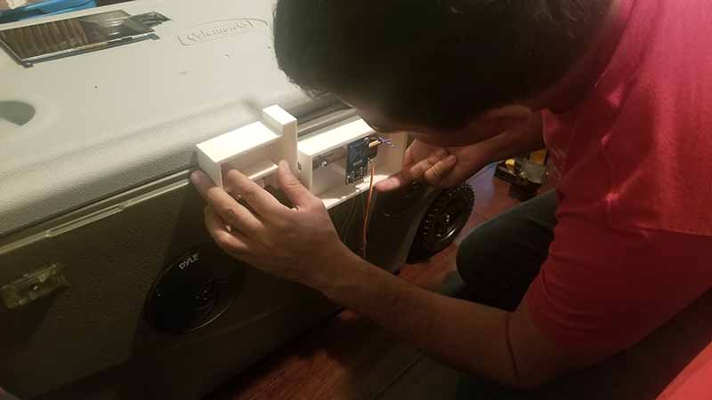
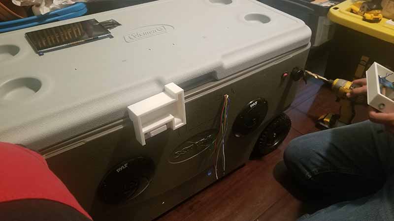
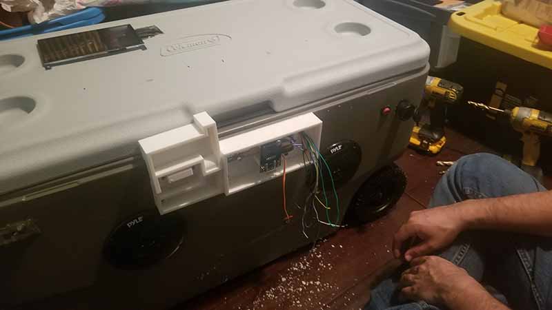
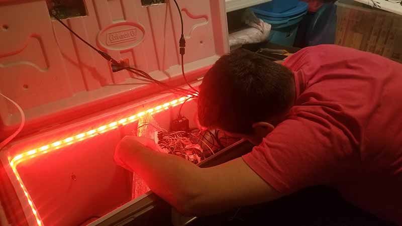
Clarence then went through the process of terminating the wires with male and female terminals so that the wires can be connected. The RFID required 7 female terminals, and the servo required 3 male terminals. The door position sensor required stranded wire. All these components would share the same ground wire, so a quick connect was used to connect 3 wires together. Two quick connects were used.
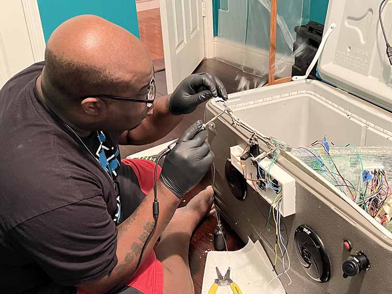
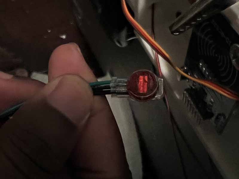
The assembly was then completed with the locking mechanism, RFID, and servo screwed in and wired up.
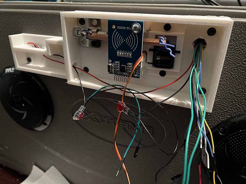
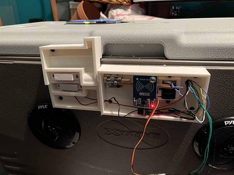
The initial attempt to test the locking mechanism did not work. The servo did not rotate and the RFID was not registering. After first checking the wiring to see if everything was connected correctly, the servo data pin was actually in the wrong slot on the breadboard. The servo was then tested and worked correctly. The RFID was then checked for wiring, and after seeing that if was wired correctly, the next assumption was that the ground wire was not connected, as quick connects were used instead of soldering the connections. After testing, it was determined that the quick connects were not creating a connection, so they were removed and the wires were then soldered instead. The continuity test passed, and after wiring the ground back up, the RFID was registering again. In this fashion the locking mechanism was working.
The following video shows the locking mechanism assembly being tested on the cooler. First, the RFID was tapped with a tag, causing the sliding lock to go into the lock position. The RFID was then tapped again to unlock the locking assembly. The lid is then opened, showing the LEDs turning on when the lid position sensor is open.
Clarence - After confirming that all of the functions were operating properly and were wired, the inner walls were closed, using a combination of foam insulation and two part epoxy. The approach used was to secure one long side then the other then finally the short ends.
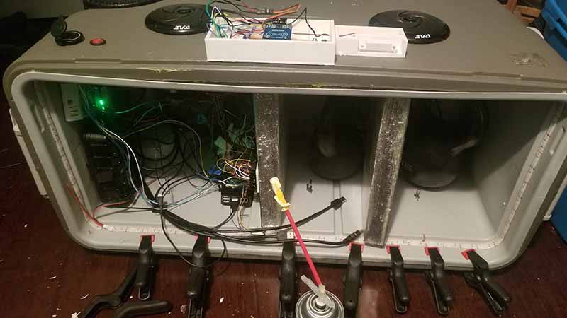
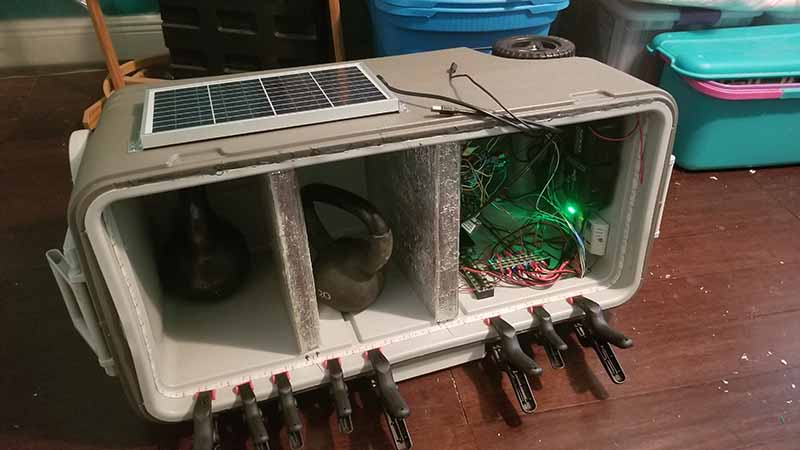
With the interior walls secured and sealed the compartment dividers were secured and using a clear silicon a water tight seal was made. With the seal made it was tested to make sure that it didn’t leak by pouring water into the far compartment.
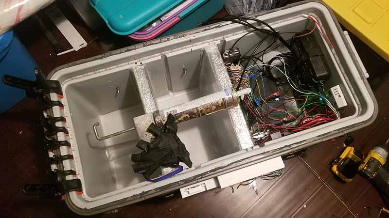
After that ice was added to the compartment to confirm that the divider and silicon aren’t affected by cold temps. It has been noted that the temp in the compartments are different but will need further testing with equipment to confirm.
Week 28 - 02/10-02/16
The group met on Saturday to go over to Lowe's and purchase material needed for the project. We purchased a metal sliding lock, weatherproofing to use as the gasket, and caulking which will be used to seal the compartments.
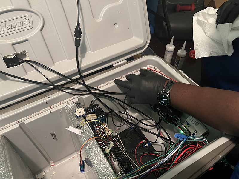
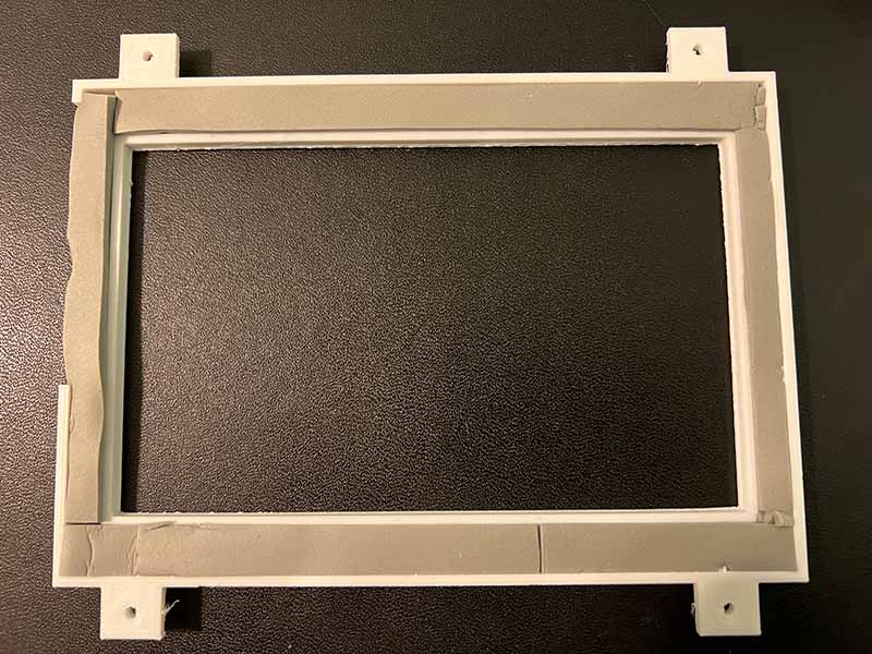
Clarence - The LED light strip was glued into place, as the adhesive that comes on the strip was not strong enough to hold on the ends. Super glue was used, and the ends were held in place until the glue held. The gasket was also cut into shape and fitted into the monitor bezel piece. It was decided for the wire cover piece that the part be reprinted to allow for tabs that make it easier to glue the pieces together.
Reuben - A couple new features were added to the GUI. A new settings screen was added to allow for more configurable features. The temperature unit settings were moved to this screen, along with two new settings, profiles and ice monitoring. The ice monitoring works detecting when the temperature has reached a certain threshold, then sending a notification. The compartment buttons are initially colored in red, meaning that ice notification has not be activated yet. First, the user places ice in the compartment. Then, the compartment is selected, and the Set button is pressed. The compartment is then colored green, this means it is activated. When the threshold is reached and the notification is closed, the compartment will reset to red indicating it is deactivated.
The following video shows how the ice notification works. The user first goes to Settings, then the More option to see the Ice Monitor setting. Compartment one is selected and then activated, indicated by turning green. In the video, fingers are placed on the temperature sensor to raise the temperature. Once the temperature hits 90 degrees, the notification will display saying the ice needs to be replaced. Going back to the settings screen, it can be seen the compartment button is red again, meaning it has been deactivated.
The user can now save and set different profiles.There are two different profile settings. First, the user selects the desired profile. Then, the user can either save the current settings as the profile, or configure the settings to the saved profile settings.
The following video shows the user first selecting Profile 2, then setting the temperature units to Fahrenheit and the LED color to Blue. In Profile 1, the temperature units is set to Celsius and the LED color is Red. The profile is then saved. Profile 1 is selected and set, changing the LED color to red and the temperature units to Celsius. Then Profile 2 is selected and set, changing the LED color to blue and the temperature units to Fahrenheit.
Finally, progress was made on the locking mechanism. The following video shows a servo with a wooden dowel attached to the arm. The other end of the dowel is attached to the knob of a metal sliding lock. The servo is programmed to rotate 90 degrees, causing the lock to slide open and closed.
Week 27 - 02/03-02/09
Reuben - The goal for the week was to get some parts 3d printed. The Crealty Ender 3 printer was used to print the parts below, using the Ultimaker Cura program to slice the models into gcode.
The lid sliding lock was attempted to be 3d printed. The locking device would be a standard sliding lock, where the parts that needed to be printed would be a sliding bar and knob, and the case. After printing, the results showed that because of the limitations of the 3d printer, it was not feasible to 3d print the part. Because the case holding the sliding bar had an open gap in between the bottom and top, the 3d printer printed support beams in between. Unfortunately, the support beams would need to be removed, and it would prove to difficult. The results are shown below.
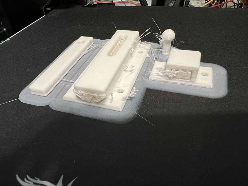
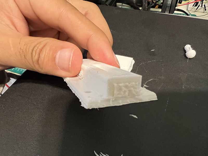
After attempting to print the sliding lock, it was decided that maybe not everything should be done in-house, so a sliding lock will be bought from the hardware store instead.
The servo bracket was also modeled and 3d printed. The bracket has just enough room for the servo to fit in place, and two screw holes so that it can be secured to the cooler. Because the servo will only be turning 90 degrees, the servo arm used only has one extended arm. The arm will have a piece of wire connected to it that extended to the sliding lock knob, giving it the action of sliding open or closed. Printing the servo bracket took approximately 1 hour and 25 minutes, using 8g of ABS plastic.
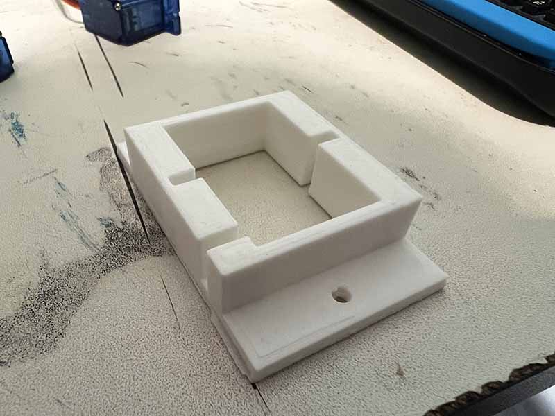
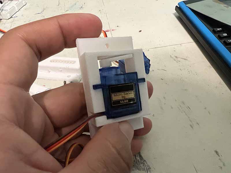
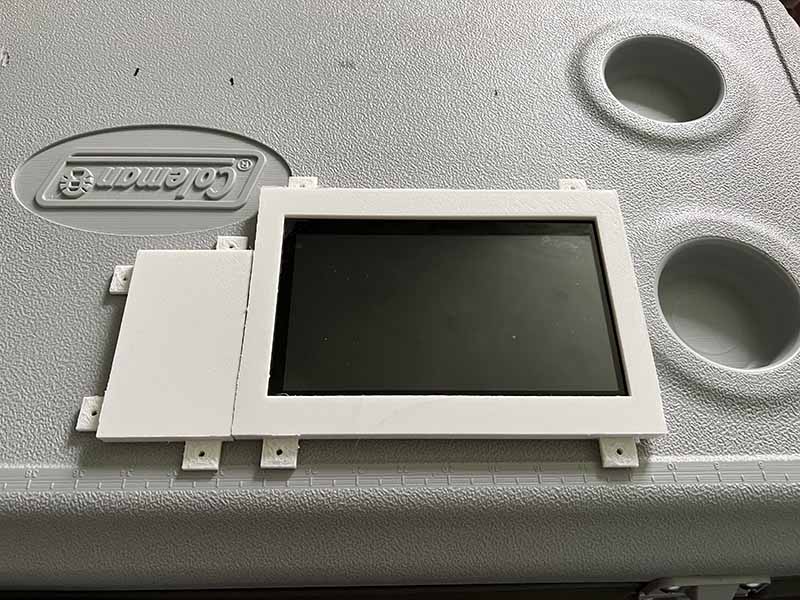
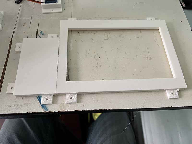
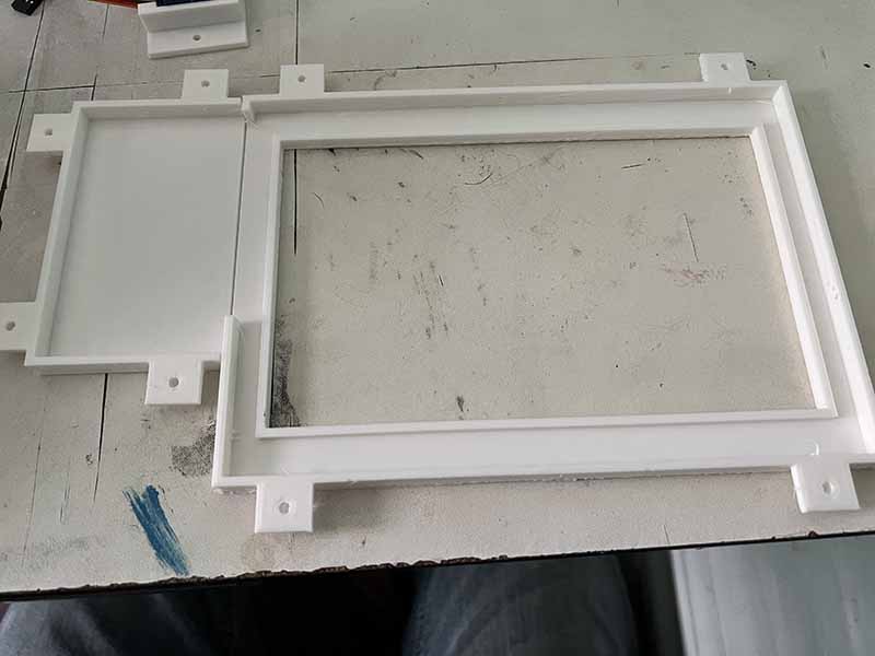
Next up was to print the monitor bezel. Because the bezel is too large to be printed as one piece using the Ender 3 printer, as the platform is only about 8in by 8in, and the monitor bezel is 5.25in by 9.75in, the piece was split into two parts. The first part wraps around the touchscreen, where a gasket will be cut to shape to allow a watertight seal. The touchscreen is approximately 6.5in by 3.9375in, so the bezel that covers the touchscreen is 7.5in by 5.25in by 0.375in.
The second part of the bezel was created to cover the HDMI and USB cables that are running through the lid. The dimensions of the wire cover are 3.75in by 2.25in by 0.375in.
The monitor bezel that seals the touchscreen took approximately 6 hours to print, using 40g of ABS plastic. The monitor wire cover took approximately 2 hours and 52 minutes, using 19g of ABS plastic.
Another thing accomplished this week is having the cooler save its configuration settings on power down. Through the use of an external text file, now when the Power button is pressed on the GUI to power down the Raspberry Pi, the state of each setting is saved into the text file named "savesettings". So now, when the Raspberry Pi is powered up, it will read the settings from the text file on start up and set each setting to its previous state before it was powered down.
Week 26 - 01/27-02/02
The group meeting was pretty straight forward, and more discussion and planning then work on the build itself. We did test the connectivity of the system and confirmed that the speakers maintain good connectivity at a range of 45 feet and is unaffected by walls. We expect similar results with the mobile app in general, but have yet to confirm. Also we confirmed that the speakers are quite loud and can be heard easily at that distance and can easily provide music outdoors at any campfire or gathering.
Clarence - Firstly I looked into designs for what is going to be our locking mechanism. After doing a fair amount of research I came across a very helpful web page and video and am using that as a starting point for our lock.
Arduino Based RFID Door Lock Make Your Own
Even though this particular project is based around an arduino, it is still very helpful and a good starting point for this function as it relates to our design.
The battery testing was rather straightforward, after fully discharging the battery through use and testing I recharged the batteries using the 120V charging cable and it took 3.5 hours to reach a full charge of 14.57 Volts.
Reuben - The project report needed to be uploaded to OneDrive so that the team could collaborate on editing the document together. With the project uploaded, a few minor changes were added to the report, including updating the Table of Contents. Now, the Table of Contents contains the modified Chapter 3, the contributions section, where all of the work implemented and troubleshooted will be added.
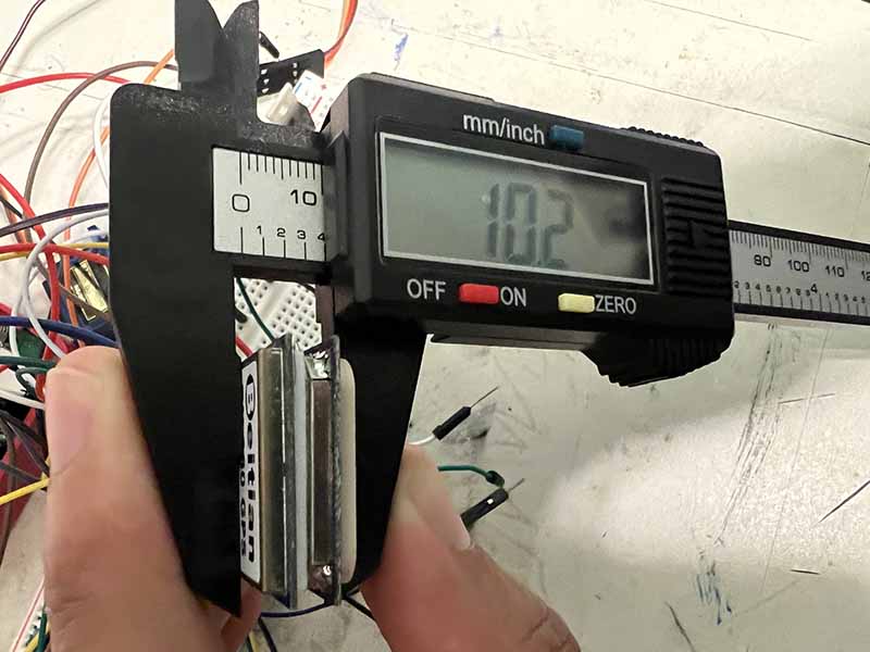
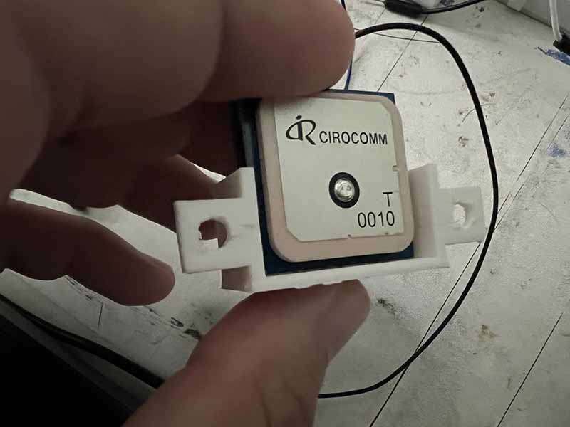
Originally, the plan for this week was to add to the software of the cooler and mobile app, but since Clarence had the cooler at his place for the week, I couldn't work on it. So instead, the focus was on fabricating a bracket for the GPS, as it has nothing to hold it in place. The GPS was measured using a digital caliper, having measurements of about 28mm x 11mm.
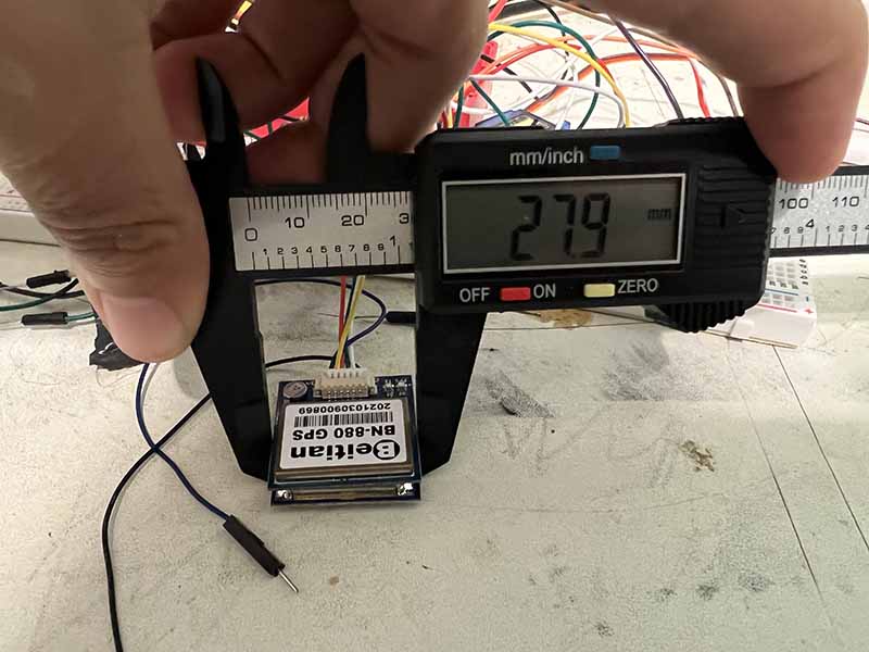
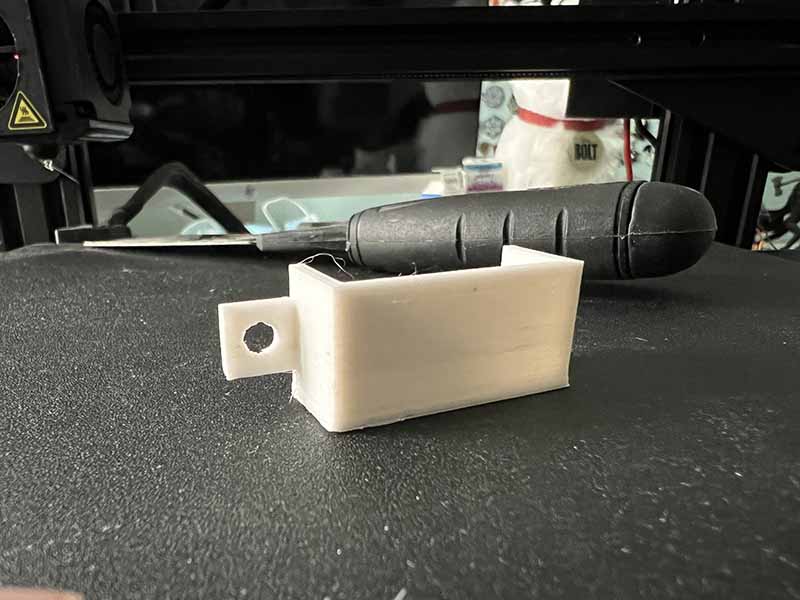
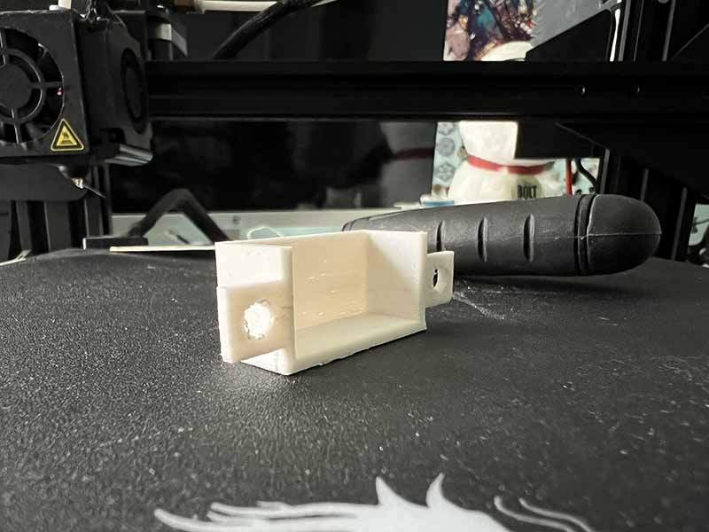
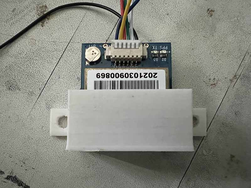
The bracket was modeled in Fusion 360, where an enclosed was modeled to hold the GPS module and tabs were extended to be able to use screws.
The bracket was 3d printed using a Crealty Ender 3 printer. The material used was ABS plastic, as ABS is more resistant to heat. Model was sliced in Ultimaker Cura to produce the gcode needed to print the model. The print took about 30 minutes, as the size of it is really small.
Week 25 - 01/20-01/26
Clarence - In order to get the speaker power button working with the Raspberry Pi, the speaker circuit needed to be split so that is goes through a switching MOSFET. Originally the 12V positive side of the speakers and amplifier were split and passed through the MOSFET, but after testing, the circuit did not work. The circuit actually needed to be split on the ground side.
The video below shows the speaker power button working from the mobile app. When the speaker power button is pressed, the speaker LEDs and amplifier turn off. When turned on, the phone reconnected with the speakers and works.
Reuben - The battery level indicator was added to the mobile phone app. The battery voltage values still need to be calibrated to give accurate battery levels but the battery level being sent from the cooler is being sent to the mobile app through bluetooth.
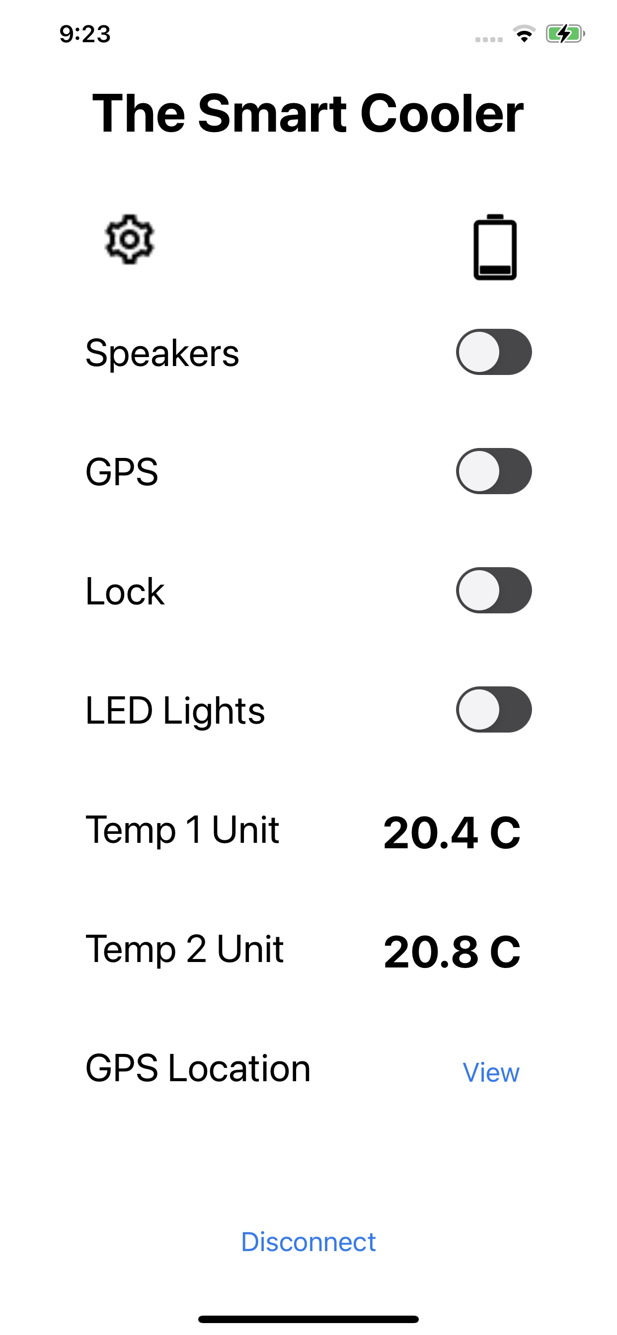
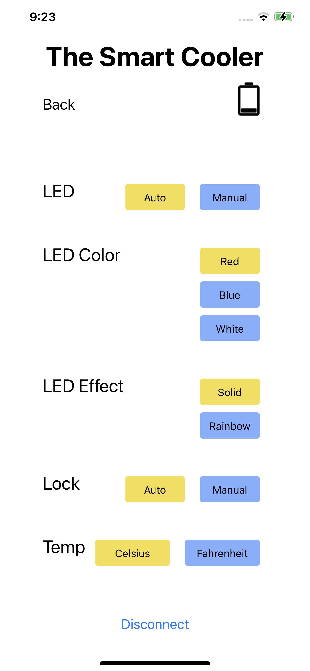
Next, the LED light strip was glued around the rim of the cooler. The strip had to be cut to length to fit, and wire needed to be extended for the power, ground, and data wires. The system was then tested through the mobile app. In the following video, the LED light strips are turned on through the mobile app. The LED light colors are then changed through the settings screen. Next, the door position sensor is shown in the closed and open position. When closed, the LED lights turn off, as the door will be closed so there is no point to have the lights on. Also, when the door position sensor is closed, then the servo can turn 90 degrees to lock. When the door position sensor is open, then the LED lights can turn on. This also applies when the lights are set in auto mode.
Week 24 - 01/13-01/19
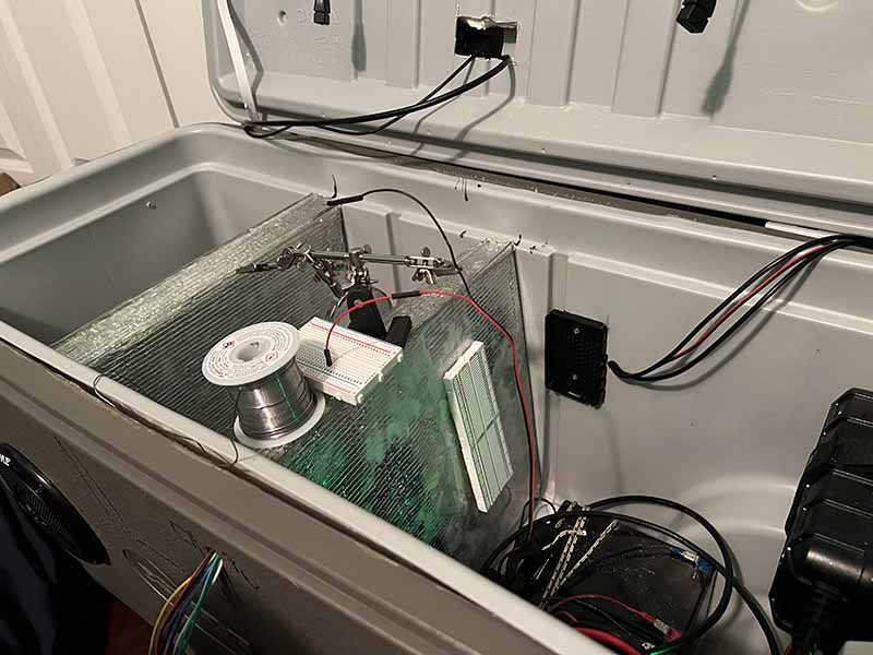
Clarence - The Raspberry Pi along with the breadboard was mounted into the cooler. The wires that were run into the cooler needed to be cut to length and soldered with male or female terminal connectors so that they could be wired into the breadboard. The temperature sensors, light sensor, and battery level indicator from the cooler were wired into the breadboard. The RFID, servo, and reed switch have not been wired into place yet until the locking mechanism that be modeled and printed. The Raspberry Pi was connected to a 12V to 5V buck converter also being used for the wireless charging. The LED light strip, servo, and GPS were being powered by a separate 12V to 5V buck converter.
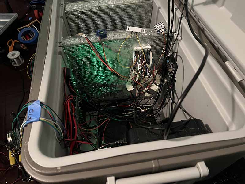
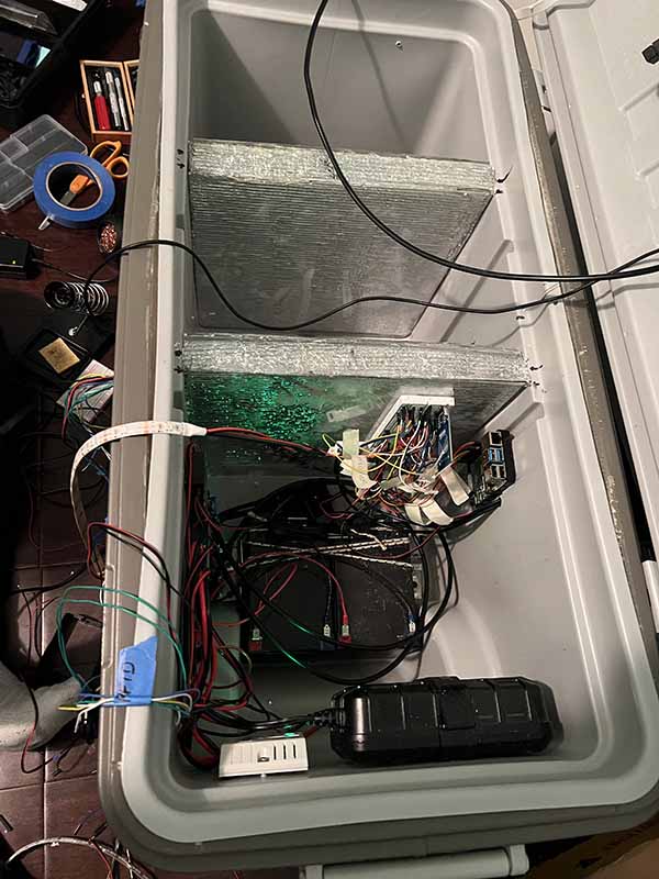
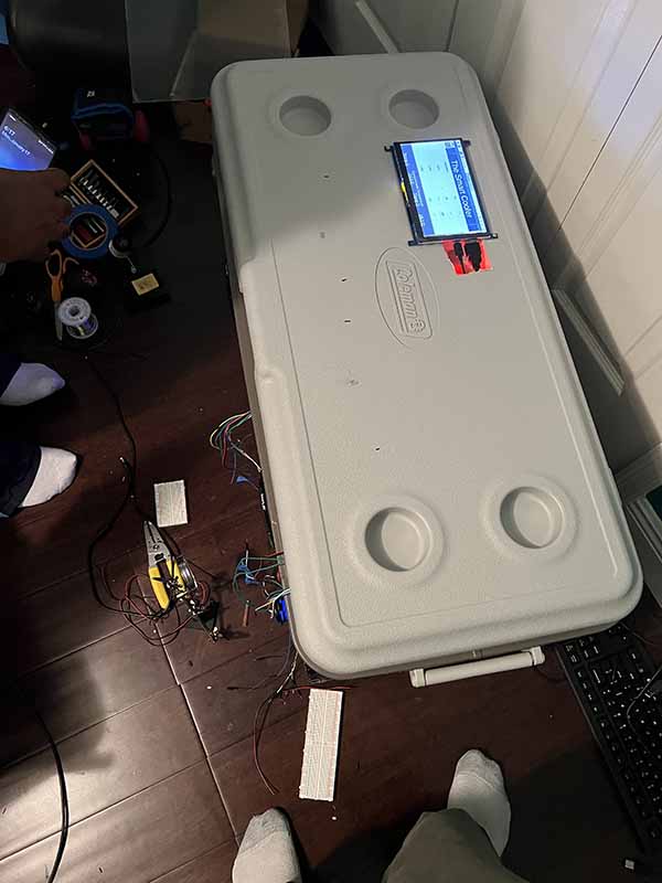
Prototypes for the monitor bezel and breadboard cover were also modeled. The monitor bezel was shaped for the touchscreen to fit into, while covering the HDMI and USB cables that extend out of the side. The breadboard cover at the moment is modeled for the wired to come out of the top or bottom of the breadboard, but may be modified later when all the components are wired in.
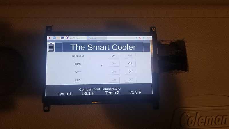
Reuben - The settings functionality of the cooler has been worked on. The cooler now has an auto and manual LED light strip mode. In auto, the cooler will use the light sensor to detect if it is dark outside, and if so the lights will be turned on. Manual allows the lights only to be controlled by the main screen on and off buttons. The color of the LED light strips can be modified to red, blue, white, or rainbow. The locking mechanism can be set to auto or manual. In auto, whenever the door position sensor is closed, the servo will rotate of the lock position. The door can be unlocked using the RFID reader, either with the keychain or card, and can also be locked and unlocked by using the on and off buttons on the main screen. The program also boots up on startup so that when the Raspberry Pi is powered, the GUI interface appears onscreen. The temperature sensor reading, light sensor, and battery level indicator are taking information from the cooler as they have been wired into the system. The RFID, servo, and door position sensor still need to be wired into the breadboard and on the cooler. A power button was also added to the program to shut down the Raspberry Pi.
The following video shows the GUI interface after bootup, the LED light strip auto feature being tested by covering the light sensor on the cooler, the LED light strip changing colors, the temperature being converted from Celsius to Fahrenheit, and the Raspberry Pi being powered down by the power button.
The following video shows the Raspberry Pi being powered, while the wireless charging is being used. The speaker are also shown to be on.