Progress Logs
Any research conducted or progress made on the project are documented in this section.
Week 23 - 01/04-01/10
Week 22 - 12/28-01/03
Week 21 - 12/21-12/27
Clarence -
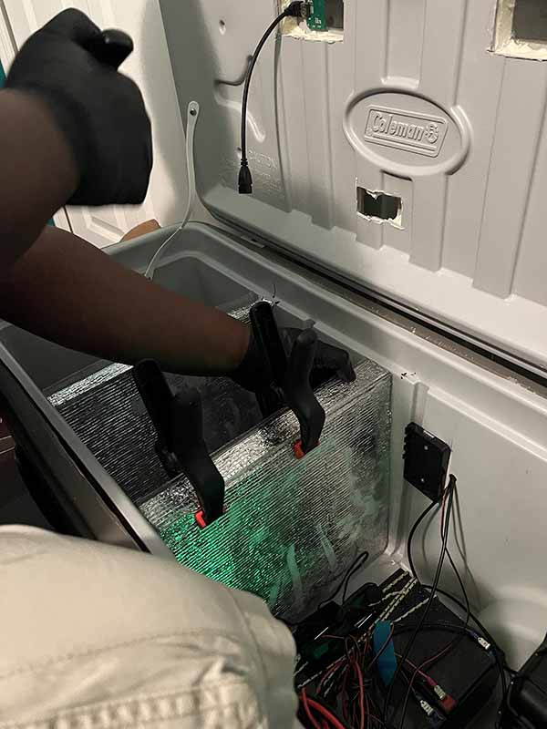
The acrylic sheets were glued to the styrofoam panels. With this complete, the next steps will be to fabricate the lids that will be used to seal each compartment.
The monitor bezel prototype was also rendered in Fusion 360. It will enclose the touchscreen, and will have a gasket around it to make sure it is sealed properly.
Week 20 - 12/14-12/20
Week 19 - 12/07-12/13
Reuben - The battery level indicator was programmed on the Raspberry Pi. At the moment it is set to show the battery level in 20% increments, from 0V to 14V. Since the batteries are 12V, but were charged up to a max of over 13V, the max level of battery voltage was set to 14V. The batteries will need to be tested to see what the lowest voltage rating it can have while still being functional.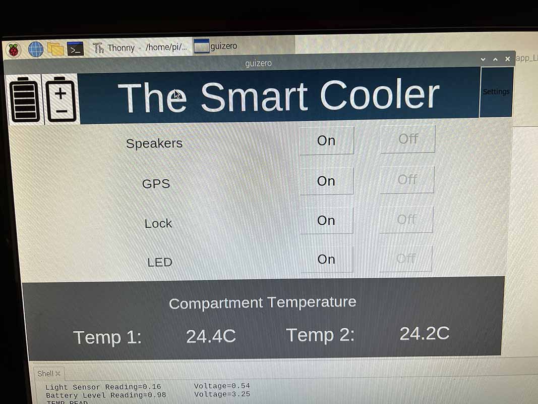
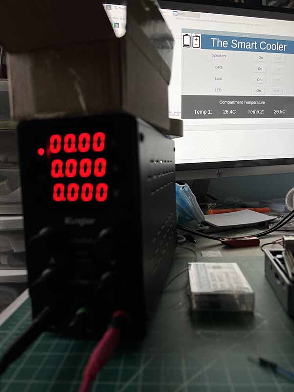
This youtube video shows that as the voltage level changes on the bench power supply, the battery level rating changed on the Raspberry Pi GUI.
Week 18 - 11/30-12/06
Week 17 - 11/23-11/29
Week 16 - 11/16-11/22
Week 15 - 11/09-11/15
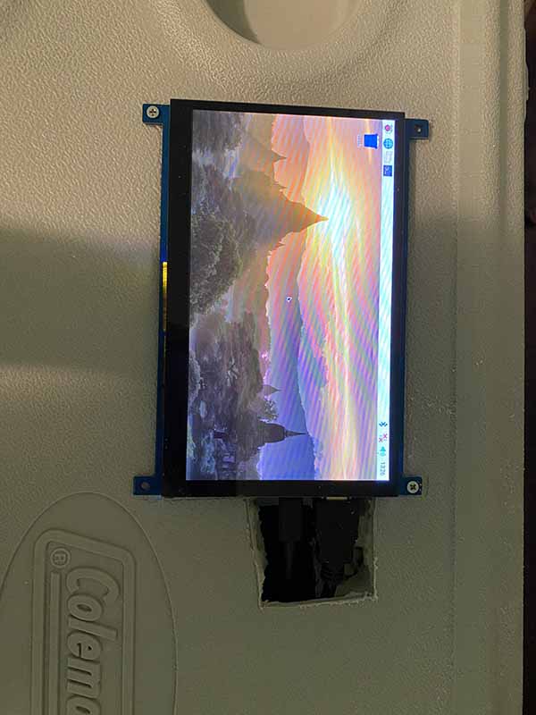
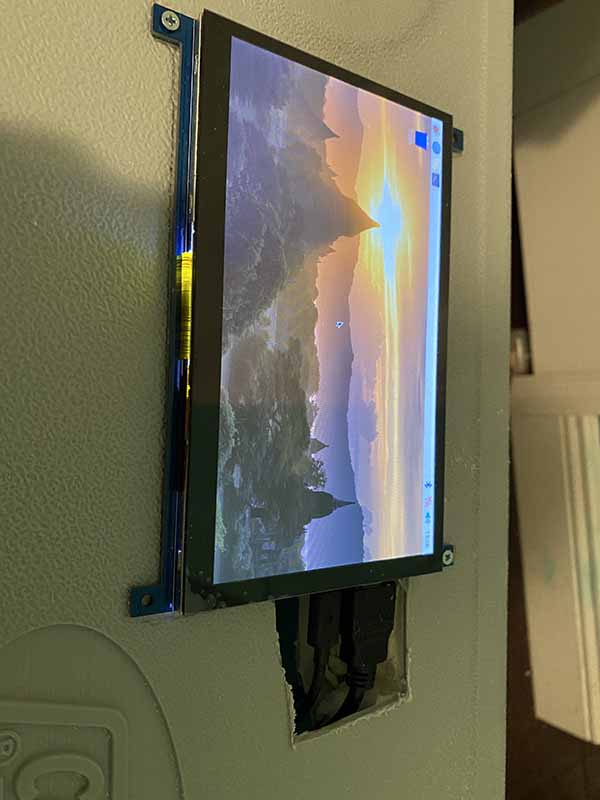
Clarence - A hole was cut on the lid to allow for the wires for the touchscreen to connect. The touchscreen was positioned and outlined so that the 3D model of the lid could be planned out.
Week 14 - 11/02-11/08
Week 13 - 10/26-11/01
Week 12 - 10/19-10/25
On Saturday we met, working on the dividers and more wiring. New plexiglass pieces were cut and sanded into shape using a dremel. The thermal wrapping was wrapped around the styrofoam and glued together. The styrofoam and thermal wrapping piece was then glued to the plexiglass, creating a stable thermal insulating structure. These pieces were placed in the cooler, not yet permanently, to help with locating position and where on the plexiglass the Raspberry Pi and other components will be mounted on it.
Clarence - The power switch was wired onto the cooler. The power switch will be used to turn off the battery source, completely cutting power to all components.
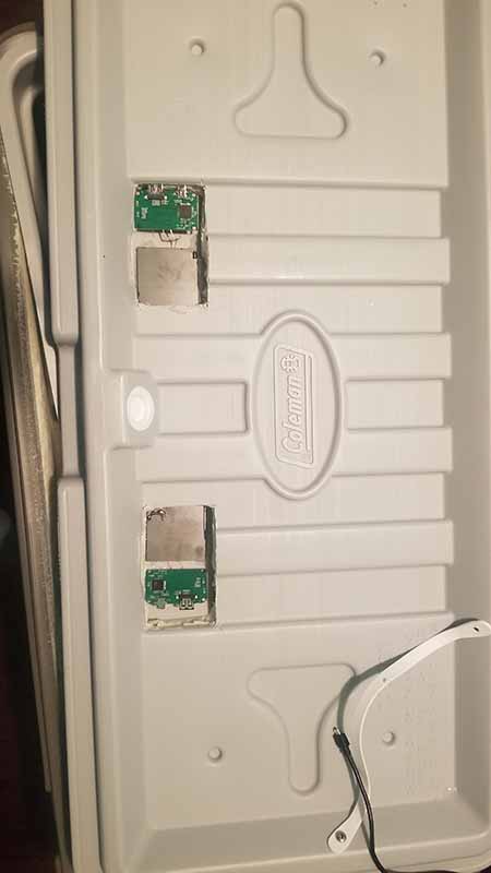
Also the lid was placed back on the cooler. The wireless charging devices were also epoxied to the cooler in permanent position. The wireless charging still needs to be either marked or labeled on top of the cooler to know where to place the phone for charging. This will possibly be done by sanding the intended area down.
Reuben - The plexiglass was tested for durability. In order to see if the plexiglass didn't shatter or become brittle while in ice, a small piece of plexiglass was placed in a pot of ice and left for 4 hours. Every hour, the plexiglass was taken out of the pot and bent to test its flexibility. After running the test, it can be concluded that plexiglass can withstand the temperature of ice and will not be compromised while in cold temperatures. The plexiglass was unaffected by the temperature.
Next, the settings screen was modified to have a more user friendly design. With the settings screen, shown below on the left, the buttons are more visible and visually pleasing, with colors to indicate which mode is selected. The selected mode will be indicated by a yellow background color, and the unselected options have a blue background. The back button was also made larger and positioned properly. On the main screen, shown below on the right, the settings cogwheel was made slightly larger, and positioned to the right of the screen.
The design of the breadboard is being recreated to be a more cleaner design. The parts will transfer over to the new breadboard, and the MOSFETs used to switch power to the devices are also being added. This new breadboard will be placed in the cooler, as it will be the final design of the breadboard.
Week 11 - 10/12-10/18
On Saturday we met to confirm that the buck converter that we bought meets the requirements of the Raspberry pi. After that we also talked and discussed how we were going to implement the dividers that would divide the cooler into the three compartments for our design.
We tested to see if the GPS would work inside the cooler container. We verified this by placing the GPS and Raspberry Pi inside the cooler. The video recorded shows that while the Raspberry Pi is inside the cooler, the GPS module still works. Though the video shows the lid open, as was needed to record the screen of the Raspberry Pi, we also tested with the lid closed. The GPS module still gave correct coordinates.
Clarence - Wire needed to be run for the locking mechanism. The RFID needed 7 wires to operate, for SDA, SDK, MOSI, MISO, RST, GND, and 3.3V. The door position sensor wire also needed to be run, which needed two wires. The servo is also going in the locking mechanism, so three wires were run for that, DATA, 5V, and GND.
The dividers for the cooler sections were also worked on. The plexiglass edges were rounded to fit into the cooler shape better. The styrofoam was cut and glued to shape, then wrapped with thermal wrap. The idea is to have the styrofoam with the thermal wrap, sandwiched between two plexiglass sheets. The plexiglass will then be secured to the cooler and made waterproof, creating our sections.
Reuben - Progress was made on the settings screen. The main screen shows a cogwheel button that leads to the settings page. Once pressed, the settings page shows available customizable properties. This includes setting the LED lights and locking mechanism to Auto or Manual mode, setting the LED color, setting the LED effect, and the temperature units. The picture on the left shows the main screen with the settings button added. The picture on the right shows the settings screen so far.
The design and the functionality of the settings screen has not been implemented yet. The idea is to make a user friendly and intuitive design. Additional Bluetooth characteristics needed to be added to accommodate the new settings features.
The servo is now programmed to work with the RFID. The system works by first waiting for an RFID object to touch the RFID module. Once it does, it then checks to see if the door position sensor is closed. If yes, then rotate the servo. The locking mechanism will be designed to have the servo activate and deactivate the lock. The first video below shows the servo working with the door position sensor closed.
Next, the servo is tested by opening the door position sensor. The video shows that when the door position sensor is open, the servo will not rotate. When it is closed, then it will rotate.
Week 10 - 10/05-10/11
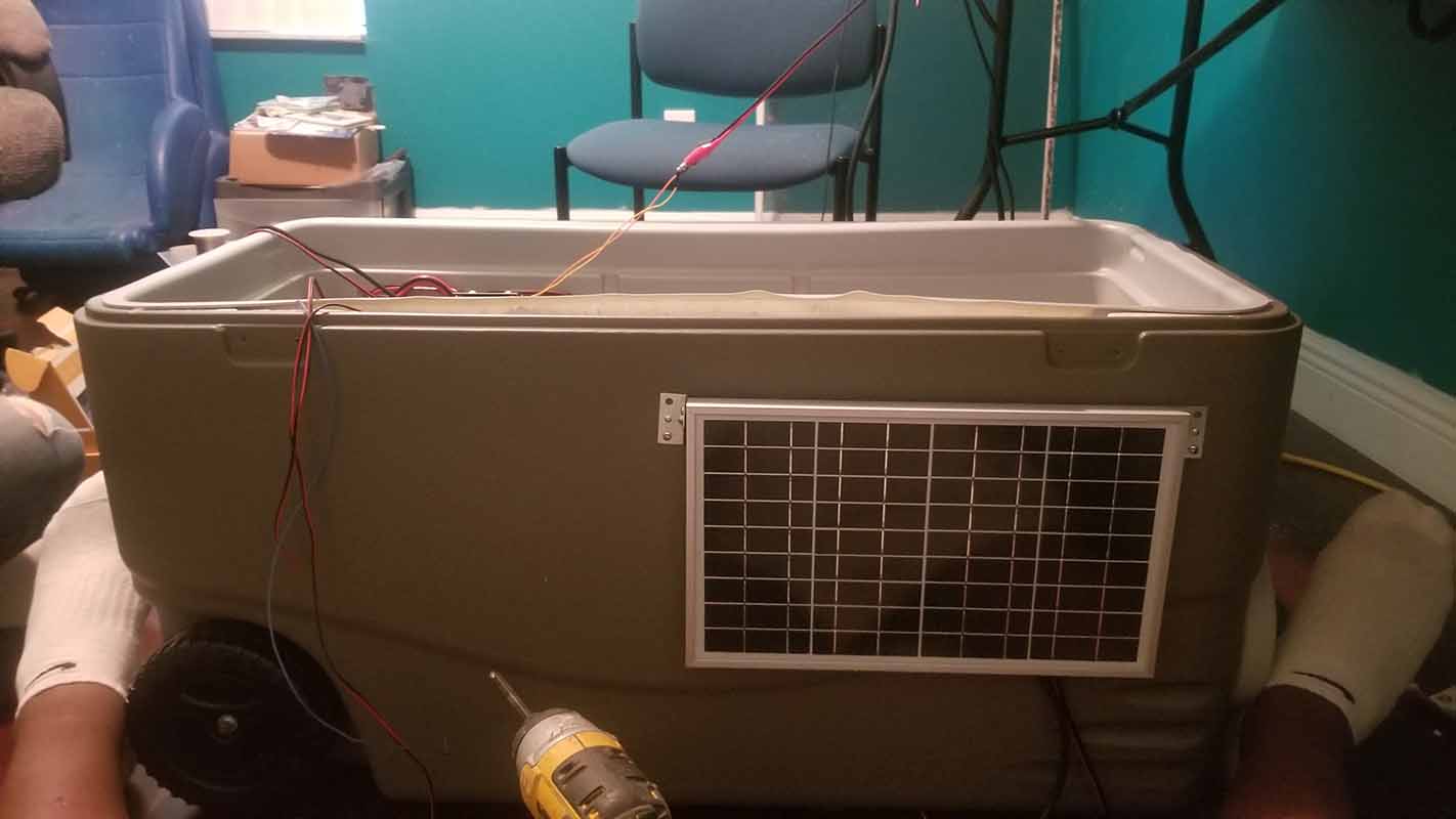
Clarence - The solar panel was wired and mounted. The frame of the solar panel featured a sturdy metal design, so self-tapping screws needed to be purchased to drill into the frame. The brackets fabricated from last week were used to hold the panel in place on the cooler. The solar was not drilled tight into the brackets, as the solar panel will be able to move freely. Parts will need to be fabricated and 3D printed to have the panel stay at a 90 degree angle to face towards the sun.
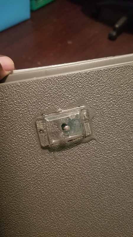
Next, the light sensor was mounted onto the cooler. The sensor was cut and soldered to the wires, and the sensor case was placed on the sensor. The case was then epoxied to make it waterproof.
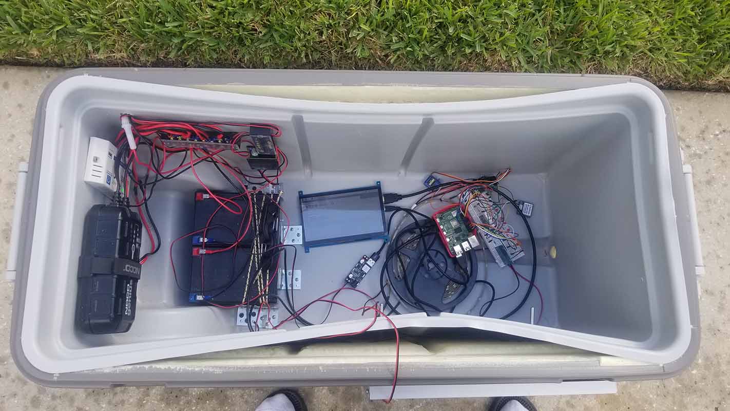
The cooler was then taken outside to test the light sensor and solar panel, just to verify that the components were working, and that there were no issues installing them. All components were running off the batteries outside. The Pi was reading sensor values from the light sensor, and the sensor was tested by placing our hand to cover the sensor and read the light value. It operated correctly.
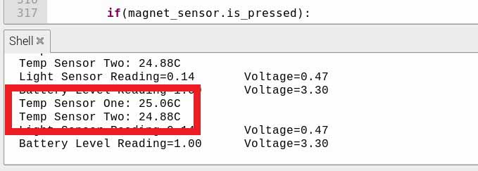
Reuben - The new waterproof temperature sensors needed to be programmed to work with the Raspberry Pi, replacing the DHT22 sensors with DS18B20 sensors. The sensors use I2C communication, and needed to have the config file modified to start communication on startup. Both temperature sensors use the same GPIO pin for data communication, along with a 4.7k resistor wired between the 3.3V power and data communication.
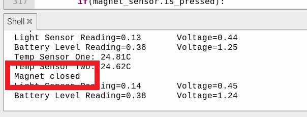
Next, the door position sensor used to detect if the door is opened or closed is a reed switch. Using the N.C. contact, when the reed switch is closed, the circuit is complete. The reed switch was wired to a GPIO input, and in python was programmed as a button with gpiozero. So when the reed switch was closed, it was "pressed", and that would print a "Magnet closed" statement in the console.
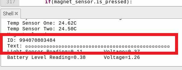
The RFID was also programmed to work. Using the SimpleRFID library, the RFID now reads the keychain or card when placed next to it. The library however needed to be modified, as the library was using GPIO 15 for the reset pin, which is being used by the GPS for TX communication, and was causing conflicts. So the reset pin was set to the correct pin. When the RFID object is placed near the RFID module, it prints the ID of the object and a text message that can be sent (maybe stored, not sure yet). This can possibly be modified later.
Finally, the battery level indicator was also obtained. The 12V battery voltage needed to be converted into a 3.3V voltage for the ADC to use. A voltage divider was used, with R2 being 22k and R1 being 6.8k, where the voltage drop across R1 would be 3.3V max at an input voltage of 14V max. Therefore, the voltage will drop from 3.3V to 0V linearly compared to 14V to 0V. Channel 1 of the ADC was used to read the voltage level.

Week 9 - 09/28-10/04
A 5V 5A buck converter was bought to power the raspberry pi off of 12V. The buck converter was tested by using a bench power supply set to 12V as well as testing it with the batteries.
This time it can be shown that the Raspberry Pi now gets supplied enough power to turn on and power the other devices, including the monitor.
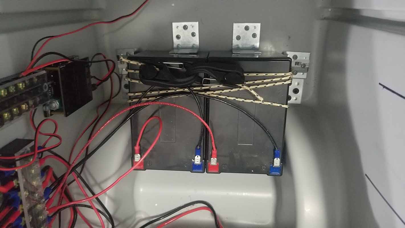
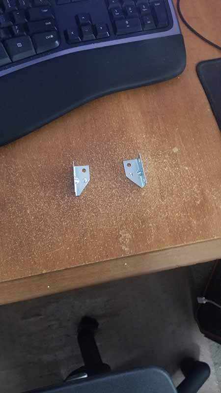
Clarence - This week the wiring was cleaned up by shortening the wire lengths. The inside of the cooler is now easier to troubleshoot with proper wiring. Next, brackets and bungee cord were bought to hold the batteries in place. The brackets are simple L brackets that allowed the bungee cord to be wrapped over the batteries to keep them in place. Additional brackets were also bought for the solar panel. These brackets were cut and shaped to hold the solar panel.
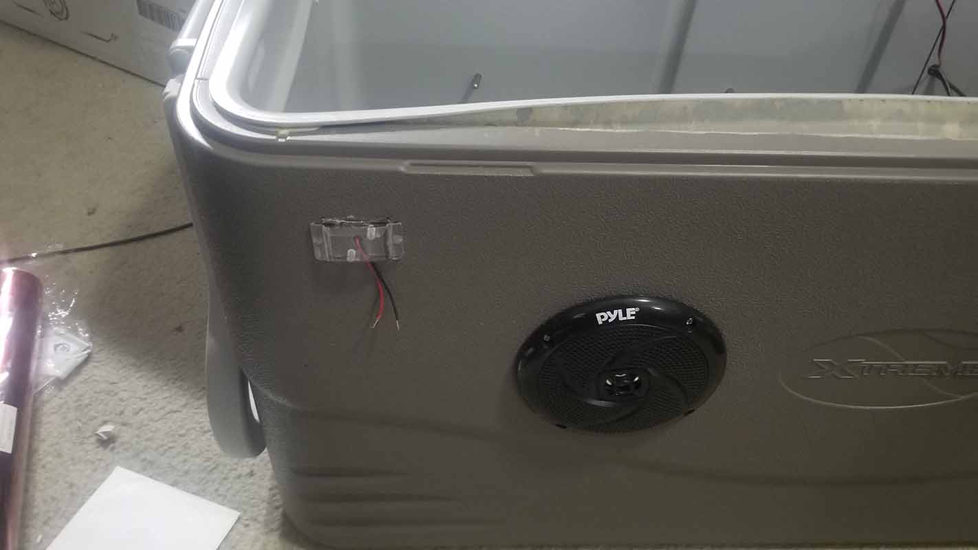
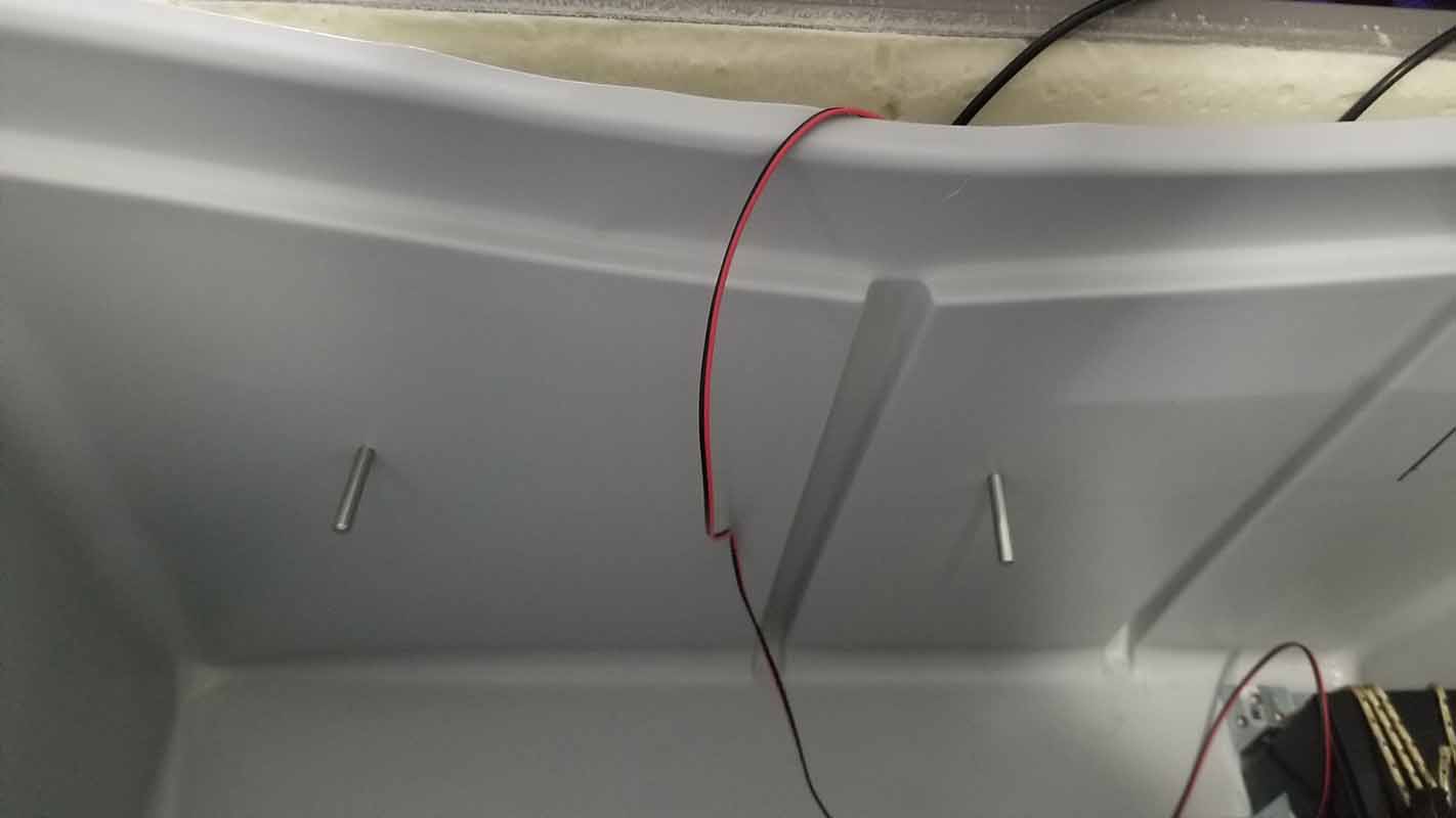
The mounting of the photoresistor case and wiring was fabricated, as well as mounting the new waterproof temperature sensors.
Reuben - Slight progress was made on the mobile app. Now when the GPS location button is pressed, the app takes you to the location of the cooler, shown on Google Maps. The settings screen is also progressing. In this screen, you will be able to change the temperature units, the LED light settings, whether the LED lights are in auto or manual, whether the locking mechanism should be in auto or manual, and other settings.
Next, all the components were tested to work in a single program. The LED lights, GPS, servo, temperature sensors, light sensor, and LED switching that will control the other components were all tested simultaneously. So far everything is working as intended.
Week 8 - 09/21-09/27
Clarence - This week went into fabrication, testing of the speakers, and buck converter testing. The speakers and amp were connected to the terminal block, receiving power from the 12V batteries. Upon powering up the speaker LEDs lit up. The amp being used was tested with an auxiliary cord and through Bluetooth to play audio through the speakers. The speakers worked as intended.
Next, the buck converter was testing by connecting it to the 12V battery supply. It will supply our 5V required for the Pi and other devices. Unfortunately, the buck converter used did not supply enough amps to the Pi, as it was having trouble starting up. The Pi requires a 5V 3amp power supply, so more amps are needed.
Reuben - This week was spent learning to redesign the appearance of the app. The mobile app now has a user friendly design. Upon opening the app, the first screen shown is the app searching for the Smart Cooler.
When the cooler is advertising, it is transmitting a unique id, or UUID. The app searches Bluetooth devices and looks for that specific id, and when found, goes to the device found screen.
The graphic in the middle is a placeholder and will be changed. The button will be a clear button to connect to the device. Once connected, the screen changes to the connected screen.
The connected screen shows what features can be modified, as well as data being sent from the Raspberry Pi. The app reads the status of found LEDs (used as placeholders for the actual devices), determining if they are on or off and sets the switch position accordingly. The temperature sensor data is also read by the app, currently set in Celsius but will be editable in settings screen. The GPS coordinates are also received by the app, however, showing the location on google maps has not been implemented yet.
Week 7 - 09/14-09/20
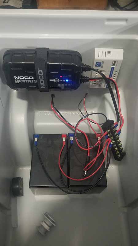
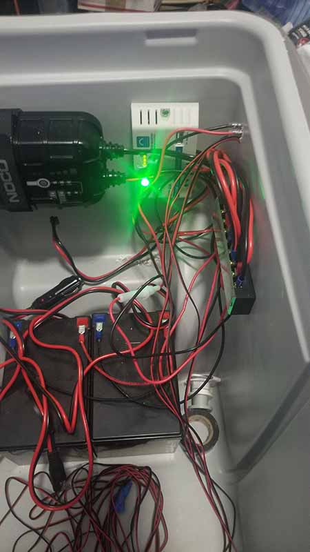
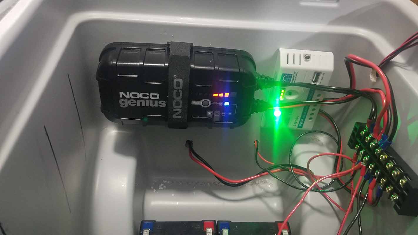
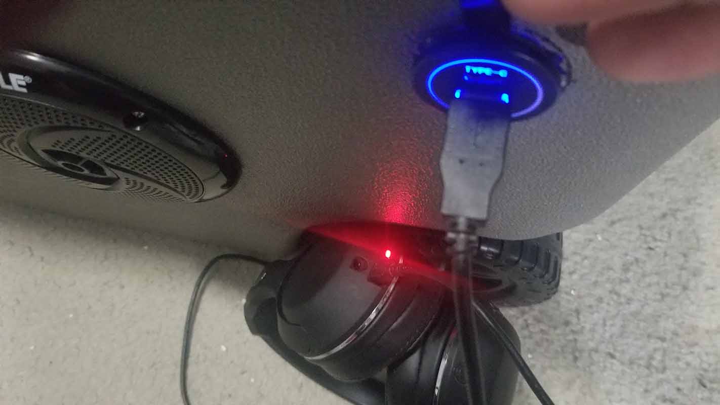
Clarence - This week several major milestones were hit. The batteries were wired up and connected 120V AC charger and demonstrated that they could indeed be charged and hold a charge safely. With the AC charging option sorted out and tested the DC side was next. The DC charger was installed and wired, also demonstrating an ability to properly charge the batteries, and from there a terminal block was used to organize the wires and connections. With that done the wired mobile device charger was connected to the output and charged several devices without incident. So as of this week we have a complete power input system and working batteries
Reuben - The majority was spent working on Chapters 1, 2 and 4 of the report. App development came to a halt as an Xcode update caused the app to have issues. Hours were spent resolving it.
Week 6 - 09/07-09/13
Clarence - The major goal of this week was to modify the 120V AC charger to safely be contained and operate in the Smart Cooler. Also as discussed the connection cable was fitted with a plug that could not be confused with the plug that will be used for the 12V DC charging function. To accomplish this I split the cable that was attached to the charger. One end was connected to the terminal block and another line was spliced to the female end of the plug that is for the AC input.
The cable then had the malel end of the plug sliced into it. With these modifications done everything was installed into the Smart cooler and tested. When it was confirmed that the charger worked, the charger was mounted.
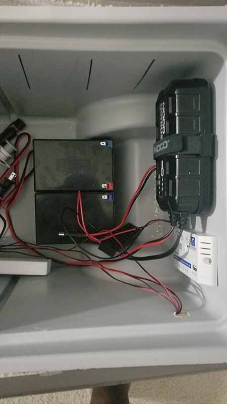
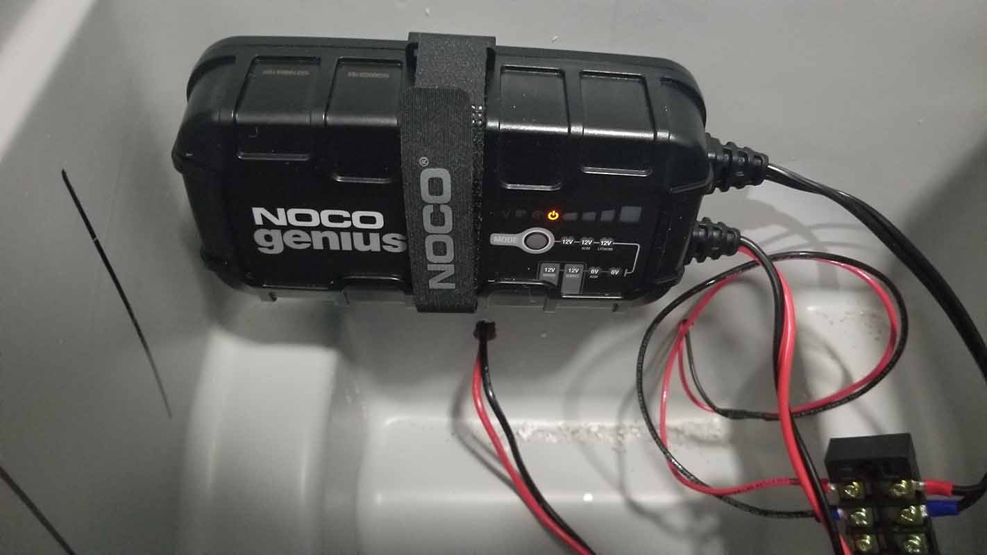
This was the main push this week.
Week 5 - 08/31-09/06
Clarence - Reviewing over what needed to be done for the report, Chapter 1 was mapped out. The following sections were added to Chapter 1: Introduction, Motivation, Objective and Features, Design Engineering Requirements, Block Diagram, Design Engineering Specifications, System Components, Power Budget, and Success Criteria. The sections were modified to take into account the revisions added after discussion with the review panel and the professor.
The terminal block was then researched to allow for the 12V and 5V needed to power the devices. A sensor cover was also found for the photosensor to be mounted to the exterior of the cooler.
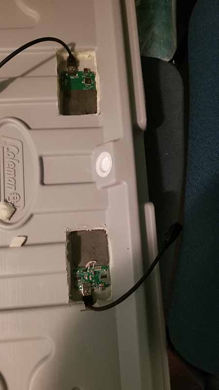
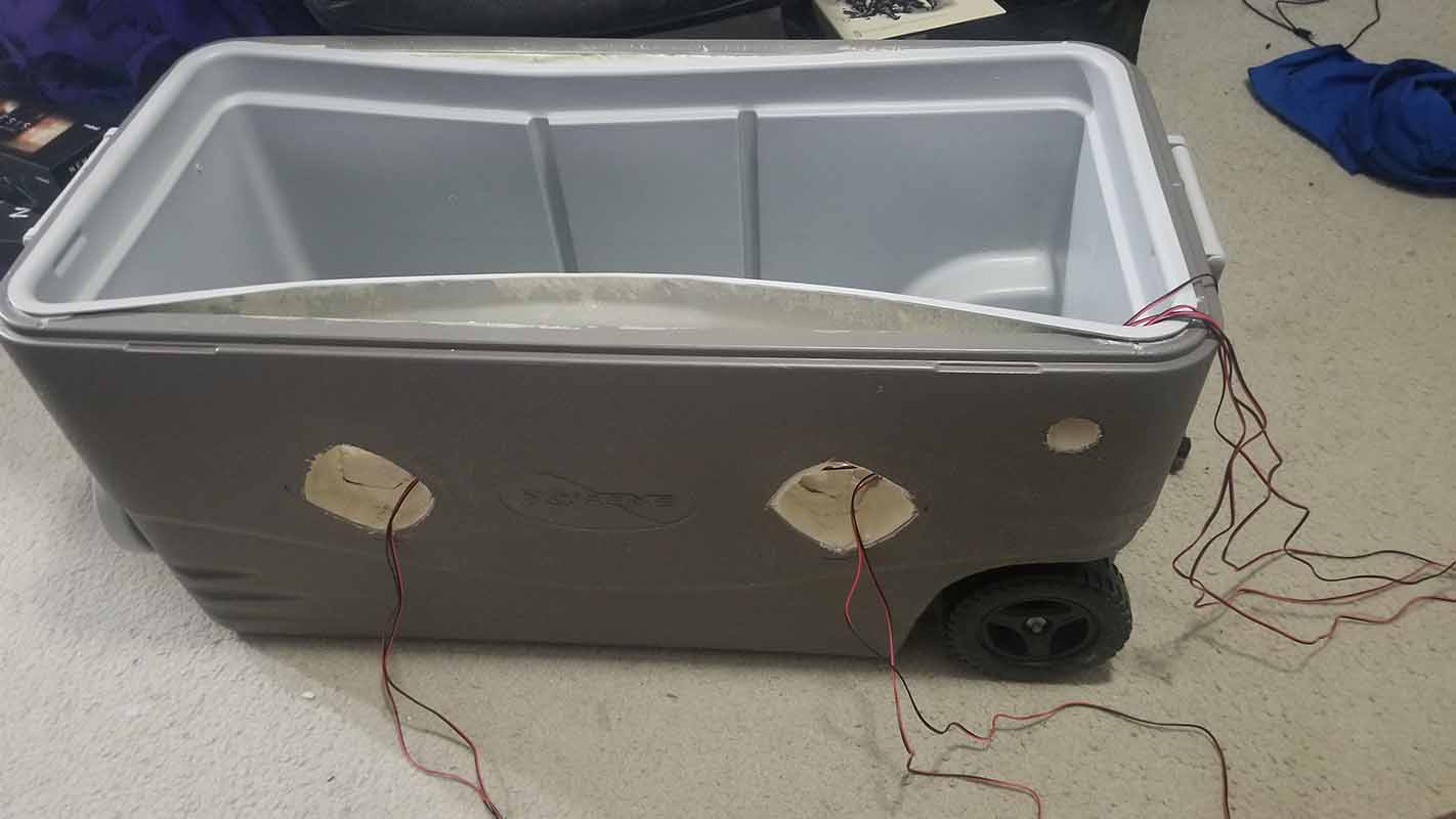
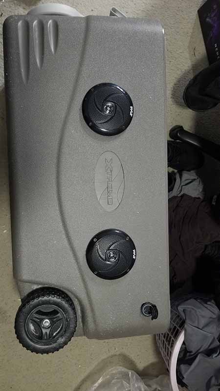
Next, the speakers and wireless charging was fabricated. The holes for the speakers were cut through the plastic and styrofoam using a dremel. For the wireless charging, the transmitters were mounted into the lid of the cooler. The lid is also solid foam, so a dremel was used to cut into the plastic and styrofoam. So when a phone is placed in the exact location, the phone will begin to charge.
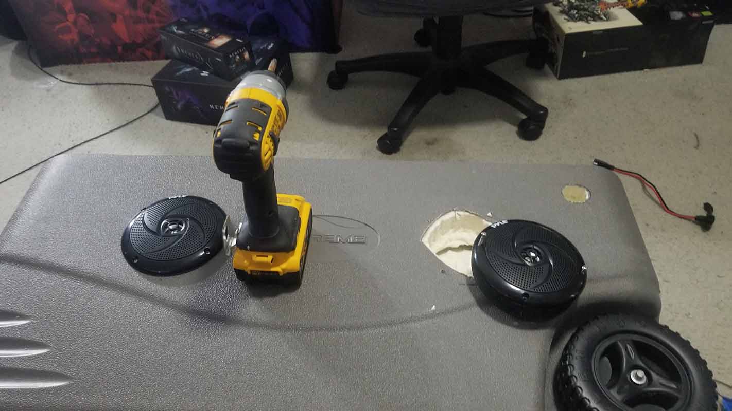
Reuben - The app was then integrated to work with iPhones. The only way to development mobile apps for the iPhone is to use an Apple computer. Using a macbook with macOS version 11.5.2, Big Sur, the iPhone version that the app was developed for is an iPhone 11 Pro Max, software version 14.7.1. In order to deploy the app for iPhone, the development environment Xcode was used. The iPhone was connected to the macbook via USB. In order to develop for iPhones, a developer account needed to be made. Once everything was done, the app could be built and deployed to the device.
The light sensor needed an analog to digital converter in order to be able to read the voltage levels. The Raspberry Pi only has digital pins, so therefore the MCP3008 ADC IC needed to be used. The library gpiozero has a class for MCP3008 ICs, and makes it convenient to code the analog readings. The photosensor uses a voltage divider, using a 1k ohm resistor and the photoresistor. The voltage of the photoresistor is read by the ADC, which allows the Raspberry Pi to be able to read the voltage level. The voltage varies between 0 V and 3.3 V, and has yet to be tested outside to get proper measurement ranges.
Next, the temperature sensors were setup using the Adafruit_DHT library.
Source: Connecting DHT Sensor with Raspberry Pi Using Python
The Adafruit library needed to be modified, as the library only works up to Raspberry Pi 3, the code for the library needed to be modified to work with the Raspberry Pi 4 by following the source tutorial above. The temperature sensors were then able to work, however when reading sensor data, they needed time to sleep in between readings, about 3 seconds. The code allows for that.
The servo was setup as well. The SG90 standard hobby servo was tested by following a youtube source of how to work a servo with a Raspberry Pi.
Source: Raspberry Pi Servo Motor Control
The servos were then tested using a loop, rotating the servo 180 degrees for 10 steps, then rotating back to its original position. The servo requires 5V, and was receiving power from a bench power supply. Note that the ground (or negative of the bench power supply), needed to be connected to the ground of the Raspberry Pi.
Finally, the LED light strip was tested. Following this source: https://tutorials-raspberrypi.com/connect-control-raspberry-pi-ws2812-rgb-led-strips/ The light strips use WS2812B RGB LEDs. They can be programmed to do different effects, and require 5V power, and a data pin for the Raspberry Pi to send data. The LEDs were measured to take a max current of 60 mA each at max brightness. In order to program for the LEDs, the audio needed to be disabled for the Raspberry Pi, as PWM would be needed for the data pin, but is also used for the Raspberry Pi audio. The LED strip length will be about 90 inches in length. To run the script, the python script must be run in the terminal using the sudo command.
The GUI was also modified to have a better look.
Week 4 - 08/24-08/30
The prototype app can scan for the raspberry pi and connect to it, so the next step was to control some GPIO pins. 6 LEDs were each connected to its own GPIO pin with a 470 ohm resistor. The GUI on the raspberry pi was updated to show 6 on and off buttons for each LED. The app was then programmed to turn the LEDs on and off, while updating the GUI of the state of the LEDs.
Week 3 - 08/17-08/23
This week we met to look over all the parts obtained. The parts include the raspberry pi, speakers, touchscreen, servos, servo controller, USB ports, car charging port, wireless charger, amplifier, buck converters, solar panel, RFIDs, bench power supply and wires.
The interior of the cooler was removed from the exterior to inspect how fabrication was going to be done. The lid was disassembled from the body as well.
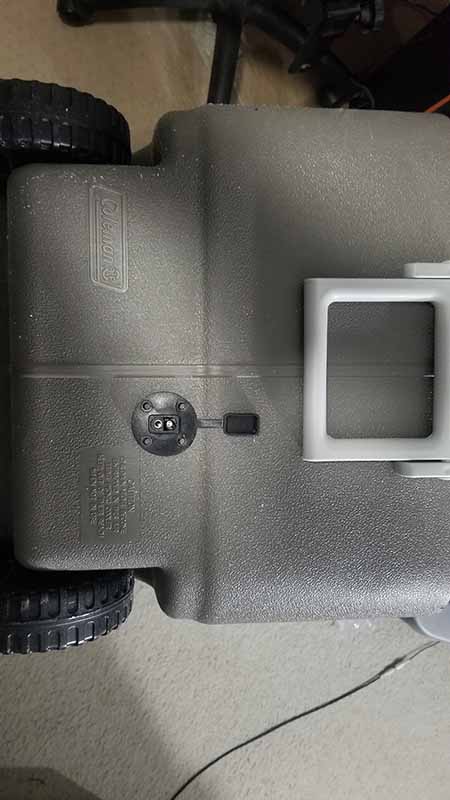
The cooler was fabricated having the speakers, USB port, and car charging port fabricated into the cooler.
Progress was made on the raspberry pi, where the pi can now act as a BLE client that is discoverable by the Bluetooth app. The app can send messages to the pi as well as receive messages from the pi. The video below shows the Bluetooth app scan for the raspberry pi. When the app connected with the raspberry pi, a message of "Reuben" is sent to the pi, which is shown on the console log.
Week 2 - 08/10-08/16
This week was spent working on the Bluetooth app in React Native and turning the raspberry pi into a BLE device that can communicate with the app. In order to program for the raspberry pi, Python needed to be learned to create the BLE script. More resources were found for this.
Creating a BLE Peripheral with BlueZ
Creating BLE GATT Server (UART Service) on Raspberry Pi
Following through the tutorials, the raspberry pi was made discoverable by the android mobile phone being used for testing and development. The test app was made in React Native to test on the android phone, learning styling, layout, buttons, graphics placement, and transitioning between screens.
The app was also build to scan for bluetooth BLE devices, showing their MAC address used for id, name, and manufacturer data.
A video was recorded of the progress of the Bluetooth app. When the start scan button is pressed, the app will scan for BLE devices for 3 seconds then output the devices found.
Week 1 - 08/03-08/09
Some of the parts needed for the project have come in. This includes the light sensors, temperature sensors, A/D converter, GPS module, Servo Controller, and wires.
Meanwhile, time was spent researching how to build the application that uses bluetooth to communicate with the raspberry pi. The programming language that is going to be used to build the app is React Native, which allows you to build the application in react native code and export it as an android and ios application using its native code.
A couple tutorials were found using the react native language, however, more research needed to be done to understand react, react native, and bluetooth technology.
So You Want to Build a Bluetooth App with React Native and Expo
MAKE YOUR FIRST IOT REACT NATIVE APPLICATION WITH BLUETOOTH LOW ENERGY
Learning more about Bluetooth discovered that there are two different Bluetooth technologies, Classic Bluetooth and Bluetooth Low Energy (BLE). BLE is used for more simple applications, such as having to turn something on or off over Bluetooth. Classic Bluetooth requires much more power. The next step was to discover how to turn the Raspberry Pi into a BLE device to be discoverable by the Bluetooth app.